• Welcome to ClassicBroncos! - You are currently viewing the forums as a GUEST. To take advantage of all the site features, please take a moment to register. It's fast, simple and absolutely free. So please join our community today!
    If you have problems registering or can't log into your account, please contact Admin.

fan wiring help needed

Sam 15

New Member
Joined
Mar 14, 2021
Messages
46
I replaced the electric fan that the PO had on as it was pretty much a hacked up fan. I got an electric fan from a 2006-2010 PT cruiser from the salvage yard with the pigtail. The PT cruiser fan has two relays wired into the harness that connects to the 4 pin pigtail that goes to the power and switch(s). Here is the same fan that's sold on ebay.

https://www.ebay.com/itm/154081534626?ssPageName=STRK:MEBIDX:IT&_trksid=p2060353.m1438.l2649

The pigtail has 4 wires...red to batt hot, black to ground and two smaller wires that power the 2 speed fan. One is for the low speed and the other for the high speed.

The smaller wires will power the fan when put to a ground. So when put to a on-off switch in the cab the fan(s) work fine. So basically, the switch interrupts a negative wire connection, meaning there is no power wire to the switch. I would like to use a 3 pin switch with an LED light (in the dash) to show when the fan(s) is on and will go off when the switch is turned off. Is there a way to wire this?

This is a good time to say that wiring is not my strong suit, so simple explanation and/or drawings would be a great help.

Rick
 

DirtDonk

Contributor
Bronco Guru
Joined
Nov 3, 2003
Messages
51,616
Well first of all, I hope it's a big enough fan! Looks kind of on the smallish side, and is meant to cool a smaller more aerodynamic and finely tuned vehicle with a 4 or maybe a 6 cylinder engine. Definitely different from a Bronco with a V8.
However, I've been pleasantly surprised at how powerful OE fans are, so hoping this one is a good find for you.
You'll know soon enough!

I would think that yes it's easy enough to connect the way you want. So you're saying that in one position the fan is on low and the other position the fan is on high? Then the third position is OFF, correct?
Seems like a simple operation since you're just switching the low power ground to switch the different relays on.

I would think that a simple switch with the one common terminal going straight to ground and the other two going to out to the other separate relays, and you'd be good to go. Just the type of lighting on the switch might be finicky.
Some have a separate light circuit, which should be simple enough to rig as well. Switched power in from the vehicle, ground to the central contact of the switch. Might need a diode to keep the motors from acting like grounds, but I think their relays would completely isolate that from happening so that your light on the switch should not be illuminated except when one of the fan positions is selected.

Seems plausible to me then. But I'm neither a switching or relaying (same thing actually) expert and there are many ways these things are wired up from the factory.
Maybe someone can confirm my conclusions, or shoot them down entirely.

But good luck!

Paul
 

DirtDonk

Contributor
Bronco Guru
Joined
Nov 3, 2003
Messages
51,616
Oh, and if you have not done so already, I would definitely make this a temporary installation test. Mount the fan, but just run the wires casually to your chosen switch, before going to all the time and trouble to bury the wires and run them cleanly. That takes a lot of time sometimes, and it'd be a shame to find out the fan is not of sufficient capacity after you've done all that work.

That's my suggestion anyway. Don't want to sound defeatist, but hate to see others go through all the trouble only to have the same results as some others that have not fared well with electric fans.

And by the way, is this just something you thought would be cool (no pun intended!) or were you experiencing a running-hot issue already?

Paul
 
OP
OP
S

Sam 15

New Member
Joined
Mar 14, 2021
Messages
46
Oh, and if you have not done so already, I would definitely make this a temporary installation test. Mount the fan, but just run the wires casually to your chosen switch, before going to all the time and trouble to bury the wires and run them cleanly. That takes a lot of time sometimes, and it'd be a shame to find out the fan is not of sufficient capacity after you've done all that work.

That's my suggestion anyway. Don't want to sound defeatist, but hate to see others go through all the trouble only to have the same results as some others that have not fared well with electric fans.

And by the way, is this just something you thought would be cool (no pun intended!) or were you experiencing a running-hot issue already?

Paul

Thanks for the input Paul. The fan is pulling enough air. I'm in Palm Desert CA and the weather has been pretty hot this summer. I've had it installed for the past 3 months. I don't drive the bronco a lot, but pretty much stays between 195-200. The fan shroud takes up the whole radiator finned area and extends about 1 1/2 inched past the bottom so I made a plate to block off the exposed area at the bottom.

I would like to install the LED switch so the switch LED goes out in case the fan(s) fail.

I have a few holes in the dash I will use for a permanent install if I can figure out how to get the switch to work the way I want. In the meantime the fan is connected to a switch plate at the bottom of the dash.

Rick
 

DirtDonk

Contributor
Bronco Guru
Joined
Nov 3, 2003
Messages
51,616
That might take either a specialty switch, specialty wiring, or something even more custom!
But it sure would be nice to have it work the way you plan.

Good to know about the fan too. Sounds like a pretty healthy one and larger than it looks in the pic. Could be another good pick for EB owners looking for an OE electric fan.

Paul
 
OP
OP
S

Sam 15

New Member
Joined
Mar 14, 2021
Messages
46
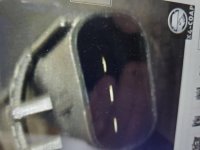
So I'm still scratching my head over this, but I think the simplest solution is to unplug the relay/switch harness from the three pin connector that goes to the fan.
The two outside pins are pos and the center pin is neg. Then wire in relays from there.
 

Attachments

  • 20210815_082030.jpg
    20210815_082030.jpg
    65.5 KB · Views: 121
OP
OP
S

Sam 15

New Member
Joined
Mar 14, 2021
Messages
46
So here's what I ended up doing to get the LED switch to work. I watched a bunch of youtube videos. One stated that the two, what I thought were relays, said that they are not relays, but switches. Isn't that what a relay is, a switch? In any case, I disconnected the plug where the fan is wired into exposing the 3 pin male connection to the fan motor (See by post above). I went the salvage yard and picked up the matching female pigtail. I wired the two positive connections together so the high speed would always be on and connected the fan to a 40A relay with an on off LED switch. I used a 30A fuse for the power connection from the battery to the relay. The power connection on the switch is wired to a keyed hot wire under the dash. Everything works the way I was trying to get it to work. I removed the rest of the old harness.

FYI Paul, the link you provided for the 3 panel switch will now work with the way I have my fan wired now. Thanks
 

Rustytruck

Bronco Guru
Joined
Feb 24, 2002
Messages
10,872
usually you want a primary fan at reduced speed and load and then a high speed fan with full power. somewhere you need a temperature switch reading water temperature somewhere in the 200 F range so when the water hits that temperature both fans come on full speed. Key ignition goes to relay for the low speed fan and powers relay for the high speed fan but goes through the temperature switch before the relay. I would wire in a back-up relay to fire the fan directly so you also have full fan control In even of relay or wire failure.
 
OP
OP
S

Sam 15

New Member
Joined
Mar 14, 2021
Messages
46
usually you want a primary fan at reduced speed and load and then a high speed fan with full power. somewhere you need a temperature switch reading water temperature somewhere in the 200 F range so when the water hits that temperature both fans come on full speed. Key ignition goes to relay for the low speed fan and powers relay for the high speed fan but goes through the temperature switch before the relay. I would wire in a back-up relay to fire the fan directly so you also have full fan control In even of relay or wire failure.

Thanks for the reply Rustytruck. I understand what you're saying, but would need and drawing to be able to understand how to wire it all together. Could you draw one and post it for me.

I guess the way I just wired the relay and switch is what you describe as a "back-up" relay. The fan is off until I activate the LED switch.

Thanks for any help you can provide.

Rick
 

Broncobowsher

Total hack
Joined
Jun 4, 2002
Messages
37,065
Some fans also are not happy being powered high and low at the same time. High or low. The low can act as a loaded generator with the output stunted by the high windings.
 
OP
OP
S

Sam 15

New Member
Joined
Mar 14, 2021
Messages
46
Thanks to all that have replied. While trying to figure out how to wire this I did a lot of goggling and you tubing. All of which were from PT Cruiser web sites where there wiring is factory and them trying to figure why they are having cooling problems and how to diagnose the problem, not how to wire them. I looked at some factory wire diagrams, but I may as well be looking a well organized bowl of spaghetti...anyway I am wiring the fan to a switch without the use of temp sending unit to turn on and off the fan. What I have gathered from goggling, is that the high speed fan will not work without the low speed fan working. So to test this, and how I came up with wiring the two pos leads together was this...as I mentioned the fan connector has 3 male spade connectors, neg in the middle and a pos on each side. When attaching the ground to the neg of the battery and the pos to the pos side of the battery. The fan comes on low speed on either side of the pos connectors. When I connect both sides of the pos spade connectors to the battery the high speed fan comes on.

So when the google web site says that the high speed fan will not come on unless the low speed fan is on, I'm taking that as if the low speed fan is not working, when the AC is turned on (to activate the high speed fan) only the low speed operates with the AC on
as in my test...Am I making any sense?

Now here's a couple of other things to note that I found while searching the web. the PT cruiser was produced from 2001-2010 in a turbo and non turbo models. The fan I am using is for a non turbo and there were no turbo models in the salvage yard. On some of the web sites they stated that the three wires connecting the fan were black yellow and green. Black for ground, yellow for high speed and green for low speed. with the fan I have the wires are black for ground and two red wires on either side. Again, the high speed mode will not come on unless the two red wires are connected. Could it be that the black yellow green wiring is for the turbo model and the black red red is for the non turbo model? Maybe wiring is different in the two models because of the turbo or the low/high speeds are controlled by the TIMP or the PCM when activated by the temp sending unit switch.

Remember I am not using a temp sending unit to activate the fan, only a on-off switch in the cab to turn on the fan. With the heat of the desert, I would rather have the high speed operating opposed to just the low speed.

So my next question, now that you have a better idea of this fan workings, can someone tell be how to wire each speed to a switch. It can either be two separate switches, one for low and one for high (but I would imagine that the high speed would have to connect to the low speed some how) or a on off on switch for each speed.

If someone can tell/show me how to make the fan speeds come on using temp sending units to activate I could try to make that work...but that's just another wiring element to throw in to what I don't already understand very well.

Thanks for reading.

Rick
 

EPB72

Contributor
Bronco Guru
Joined
Jul 13, 2019
Messages
1,207
Loc.
Pleasant Hill, CA
Thanks to all that have replied. While trying to figure out how to wire this I did a lot of goggling and you tubing. All of which were from PT Cruiser web sites where there wiring is factory and them trying to figure why they are having cooling problems and how to diagnose the problem, not how to wire them. I looked at some factory wire diagrams, but I may as well be looking a well organized bowl of spaghetti...anyway I am wiring the fan to a switch without the use of temp sending unit to turn on and off the fan. What I have gathered from goggling, is that the high speed fan will not work without the low speed fan working. So to test this, and how I came up with wiring the two pos leads together was this...as I mentioned the fan connector has 3 male spade connectors, neg in the middle and a pos on each side. When attaching the ground to the neg of the battery and the pos to the pos side of the battery. The fan comes on low speed on either side of the pos connectors. When I connect both sides of the pos spade connectors to the battery the high speed fan comes on.

So when the google web site says that the high speed fan will not come on unless the low speed fan is on, I'm taking that as if the low speed fan is not working, when the AC is turned on (to activate the high speed fan) only the low speed operates with the AC on
as in my test...Am I making any sense?

Now here's a couple of other things to note that I found while searching the web. the PT cruiser was produced from 2001-2010 in a turbo and non turbo models. The fan I am using is for a non turbo and there were no turbo models in the salvage yard. On some of the web sites they stated that the three wires connecting the fan were black yellow and green. Black for ground, yellow for high speed and green for low speed. with the fan I have the wires are black for ground and two red wires on either side. Again, the high speed mode will not come on unless the two red wires are connected. Could it be that the black yellow green wiring is for the turbo model and the black red red is for the non turbo model? Maybe wiring is different in the two models because of the turbo or the low/high speeds are controlled by the TIMP or the PCM when activated by the temp sending unit switch.

Remember I am not using a temp sending unit to activate the fan, only a on-off switch in the cab to turn on the fan. With the heat of the desert, I would rather have the high speed operating opposed to just the low speed.

So my next question, now that you have a better idea of this fan workings, can someone tell be how to wire each speed to a switch. It can either be two separate switches, one for low and one for high (but I would imagine that the high speed would have to connect to the low speed some how) or a on off on switch for each speed.

If someone can tell/show me how to make the fan speeds come on using temp sending units to activate I could try to make that work...but that's just another wiring element to throw in to what I don't already understand very well.

Thanks for reading.

Rick
That fan works as you said ground and one of the leads with power is low speed and both with power is high speed no problem with that the 2 speed keep liberty fan operates the same way ,,,, as for a fan switch the BMW coolant fan switch is a good option it's a dual temp switch there two different one they have two different heat switch points..it's a three terminal 1 to ground 1 to control low speed relay and the 3 rd to control the high speed .. the switch will have continuity to one lead at a certain temp and when it reaches the high temp it will have continuety on both Â…. Don't have time right now to get into it but google bMW fan switch
 

EPB72

Contributor
Bronco Guru
Joined
Jul 13, 2019
Messages
1,207
Loc.
Pleasant Hill, CA
Also to add turner motor sports is a good source for the switch and they also had the individual wire pigtails for that switch
 
OP
OP
S

Sam 15

New Member
Joined
Mar 14, 2021
Messages
46
Thanks for that input EPB72. I looked up the BMW part and googled some more. I may try that route. For now I will keep the fan on a manual switch. I may try to wire each speed individually on manual switches in the cab. I assume that I would wire each speed to a separate switch and relay for each speed and power both relays tied together using the 30 pin to the battery, but for the time being, the fan is working on high speed.

Rick
 
Top