- Joined
- Dec 20, 2022
- Messages
- 16
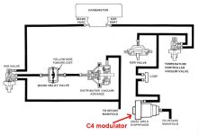
I just rebuilt my 74 302 with a 2BBL, I took pictures before disassembly and no longer have them. I would like to know how to run the vacuum lines as it was done originally but can't find any diagrams anywhere


Thank you very much, i am beginning to think it is the fusable link. I have a picture from when i took it apart last year and there was a red wire going from the battery side of the starter sylenoid through the firewall, basically by-passing the harness all together. I will take a couple pictures and try and post them, thanks so muchWell, 71, and later is pretty much the same layout. Different connector styles in many cases, but the same basically layout.
Are you reusing all the original wires? Or is this a new harness?
On the original really are only a couple of connectors that you could’ve left apart on that. Where it goes through the ammeter on the back of the gauge cluster there is a big connector on the black wire. Sounds like it is connected though, or literally nothing else would work.
It’s very possible that the wire has a blown fusible link. That’s that little bit at the end where the ring terminal is.
Do you have a couple of pictures that you can show us of the area around the battery, alternator, starter, relay, and surrounding areas?
Maybe it’s something obvious one of us can pick out.
Something else you can test, though, is how the regulator is connected. Do you have three, or four wires at the regulator? Have you tested to make sure that you have battery power on the yellow, and switched power on the green with red?
Your bronco should only have three of the four connections with wires on them.
Thank you very much, i am beginning to think it is the fusable link. I have a picture from when i took it apart last year and there was a red wire going from the battery side of the starter sylenoid through the firewall, basically by-passing the harness all together. I will take a couple pictures and try and post them, thanks so much
Well, 71, and later is pretty much the same layout. Different connector styles in many cases, but the same basically layout.
Are you reusing all the original wires? Or is this a new harness?
On the original really are only a couple of connectors that you could’ve left apart on that. Where it goes through the ammeter on the back of the gauge cluster there is a big connector on the black wire. Sounds like it is connected though, or literally nothing else would work.
It’s very possible that the wire has a blown fusible link. That’s that little bit at the end where the ring terminal is.
Do you have a couple of pictures that you can show us of the area around the battery, alternator, starter, relay, and surrounding areas?
Maybe it’s something obvious one of us can pick out.
Something else you can test, though, is how the regulator is connected. Do you have three, or four wires at the regulator? Have you tested to make sure that you have battery power on the yellow, and switched power on the green with red?
Your bronco should only have three of the four connections with wires on them.
original wire harness, new alternator and voltage regualator. Fat green and black wire under dash that has constant power with two female connectors branching out not connected to anything. Voltage regulator has one orange wire, then a green one with a red stripe and the third has two yellows. One yellow going to round condensor (not sure thats the correct name) but bolts up to regulator at fire wall. It runs fine, just no charge. More and more i am thinking fusable link. Starter cylenoid does have the wire connected to post with battery cable and that is the one that would have the fusible link. Where does this wire go without having to unravel everything, i believe it splits, one goes to regulator and then other to the dash someplace and back to alternator. I took pics but am not smart enough to figure out how to attach themWell, 71, and later is pretty much the same layout. Different connector styles in many cases, but the same basically layout.
Are you reusing all the original wires? Or is this a new harness?
On the original really are only a couple of connectors that you could’ve left apart on that. Where it goes through the ammeter on the back of the gauge cluster there is a big connector on the black wire. Sounds like it is connected though, or literally nothing else would work.
It’s very possible that the wire has a blown fusible link. That’s that little bit at the end where the ring terminal is.
Do you have a couple of pictures that you can show us of the area around the battery, alternator, starter, relay, and surrounding areas?
Maybe it’s something obvious one of us can pick out.
Something else you can test, though, is how the regulator is connected. Do you have three, or four wires at the regulator? Have you tested to make sure that you have battery power on the yellow, and switched power on the green with red?
Your bronco should only have three of the four connections with wires on them.
Thank you, i will give that a shot and see what i get.I would’ve suspected the visible link as well, but the fact that you can start the engine means the fusible link is still working. Otherwise, you would have no power to the ignition switch.
You should be able to pull the connector off of the regulator and test for voltage at the yellow wire. Should have power all the time.
Full battery voltage.
While the connector is off, also test the green with red stripe wire. Should have power only when the key is in the on position.
Green with black is accessory power. Should not have power all the time. As far as I know, anywhere on the truck up, black with green wire is accessory only.
I’ll have to revisit the diagrams to be sure, but that standard practice.
Would like to know more about this wire. Doesn’t sound familiar. Any chance you can get pictures of it?Fat green and black wire under dash that has constant power with two female connectors branching out not connected to anything.
That is correct for your bronco.Voltage regulator has one orange wire, then a green one with a red stripe and the third has two yellows.
Correct. Condenser is one correct word for it. It’s actually a capacitor (so is a condenser as a matter of fact ) and is known as a “radio noise, suppressor“ in lots of shop manuals.One yellow going to round condensor (not sure thats the correct name) but bolts up to regulator at fire wall.
As I think you mentioned previously, it’s connected directly to the alternator. Well, “directly” is a euphemistic term.Starter cylenoid does have the wire connected to post with battery cable and that is the one that would have the fusible link. Where does this wire go without having to unravel everything?

The part that goes to the regulator is just a yellow wire that is spliced into the black one. It senses battery voltage so that the alternator knows how to work how much to put out.believe it splits, one goes to regulator and then other to the dash someplace and back to alternator. I took pics but am not smart enough to figure out how to attach them
I did this test, the yellow always has power.I would’ve suspected the visible link as well, but the fact that you can start the engine means the fusible link is still working. Otherwise, you would have no power to the ignition switch.
You should be able to pull the connector off of the regulator and test for voltage at the yellow wire. Should have power all the time.
Full battery voltage.
While the connector is off, also test the green with red stripe wire. Should have power only when the key is in the on position.
Green with black is accessory power. Should not have power all the time. As far as I know, anywhere on the truck up, black with green wire is accessory only.
I’ll have to revisit the diagrams to be sure, but that standard practice.
There should be a bullet connector behind speedo that allows the charge circuit to be run thru loop in ammeter, and connected. It is BK/YE and BK/RD wires in my 68.. . . . .I believe the loop that goes from the Battery post on the alternator up through the gauge cluster in the dash and back to the starter relay/sylenoid has a connection that may not be completing a circuit. . . . .

It is possible this red wire was used to feed aux circuits (stereo, lights).. . . . I have a picture from when i took it apart last year and there was a red wire going from the battery side of the starter sylenoid through the firewall, basically by-passing the harness all together. . . . . .
The wire from the battery terminal on the alternator goes to a three prong plug that is next to the battery. The wire in this plug goes through the harness into the dash and does not go straight to the battery post on the starter sylenoid.
There are only twoi wires hooked to battery post on the starter sylenoid, the positive battery cable and the fusible link wire that goes from the harness to the dash.

Would like to know more about this wire. Doesn’t sound familiar. Any chance you can get pictures of it?
That is correct for your bronco.
Correct. Condenser is one correct word for it. It’s actually a capacitor (so is a condenser as a matter of fact ) and is known as a “radio noise, suppressor“ in lots of shop manuals.
Often a similar one connected to the positive side of the ignition coil.
As I think you mentioned previously, it’s connected directly to the alternator. Well, “directly” is a euphemistic term.
It runs from the starter relay/solenoid up through the firewall around the dash to variously power the ignition switch, headlight switch, and fuse panel, Then back out through the firewall and down to the alternators BAT terminal.
It’s basically one long loop around the middle of the vehicle.
The part that goes to the regulator is just a yellow wire that is spliced into the black one. It senses battery voltage so that the alternator knows how to work how much to put out.
Speaking of the alternator and regulator… Here is how they should be connected.
Regulator:
F = Orange field wire.
S = Green w/red “switched” wire.
A = Yellow (2) “always hot“ wire and radio noise suppressor wire.
Back of the alternator:
BAT = Black charge wire.
FLD = Field wire.
STA = Stator wire.
GRD = Ground wire.
The orange field wire should be connected directly to the FLD terminal on the back of the alternator.
The black BAT wire should be connected directly to the BAT terminal.
The white with black STA wire (if used) should be connected directly to the STA terminal on the back of the alternator.
The ground wire can be connected to any of the convenient grounding studs connected directly to the case of the alternator.
Most of the time the one marked with the GRD letters is not convenient so you have to use one of the others.
The ground wire is connected to the metal tab that is part of the original alternator harness strain relief. If yours is missing or damaged, you can make your own if you need to.
On your rig, the white with black stator wire is used only to power the electric choke on the factory original carburetor.
If you don’t have that anymore, you can disregard that wire.
But make sure that the orange wire is connected to the FLD terminal, the black wire is connected to the BAT terminal, and the ground wire is connected to one of the GRD terminals.
Just so you know, in case you run across it in other non-Bronco diagrams, the F was always for “field”, the S was for “stator”, the A was for “armature”, and the I was for “ignition”, or “indicator”.
Those words don’t work for Broncos or other Ford vehicles using an ammeter, so I just use switched and always for my reminder /memory words
I would’ve suspected the visible link as well, but the fact that you can start the engine means the fusible link is still working. Otherwise, you would have no power to the ignition switch.
You should be able to pull the connector off of the regulator and test for voltage at the yellow wire. Should have power all the time.
Full battery voltage.
While the connector is off, also test the green with red stripe wire. Should have power only when the key is in the on position.
Green with black is accessory power. Should not have power all the time. As far as I know, anywhere on the truck up, black with green wire is accessory only.
I’ll have to revisit the diagrams to be sure, but that standard practice.
thanks for the input.As Paul stated, if you can start the Bronco, power is flowing from battery, thru fusible link, to starter switch.
I would suspect "new" alternator and / or regulator.
Check grounds;
from battery to block (should be good if starter is working)
from block to alternator
from alternator to fender (regulator mount).
I would add one from battery to fender.
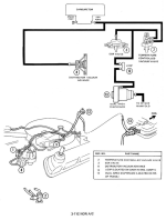
There should be a bullet connector behind speedo that allows the charge circuit to be run thru loop in ammeter, and connected. It is BK/YE and BK/RD wires in my 68.
View attachment 915562
It is possible this red wire was used to feed aux circuits (stereo, lights).
This is actual harness colors in my 68.
You have an included fusible link where BK wire connects to starter relay.
I don't think the 74 has the bulkhead connectors, and your wire colors may very.
The basic charge circuit is similar for all years.
View attachment 915565

thank you very much for your help, much appreciated and will let you know how it turns out!Fix the green with red wire first before you do anything else.
Even though new, no longer means good, at least you have had the alternator tested so we know that (at least under some circumstances) it works just fine.
So get power to that green with red wire and see if it starts charging.
Without it, the regulator won’t tell the alternator to start charging and nothing happens.
There is always the full Fielding test to see if the alternator will work, but you don’t need to perform that at the moment because you already know that the green with red S wire is not doing its job. Even if that’s not the current problem, it needs to be fixed.
But there’s a very high probability that that’s the only issue right now.
i have looked at alot of wire diagrams but have not seen this one and i think you are zeroing in on it, i couldnt find the red and yellow wire when trying to hook up that brake warning lamp, looks like i will be un wrapping my harness under the dash and probably finding where i went wrong. Thanks again for the help!Looks like GR/RD has a connector (C-206) somewhere between ignition switch and regulator connector.
Might be able to check for power on purple wire at throttle control solenoid.
Here is a link to seabuscuit68's schematics.
[/URL]
View attachment 915567
i would have sent you pictures like you asked, but i can figure how to attach them.Fix the green with red wire first before you do anything else.
Even though new, no longer means good, at least you have had the alternator tested so we know that (at least under some circumstances) it works just fine.
So get power to that green with red wire and see if it starts charging.
Without it, the regulator won’t tell the alternator to start charging and nothing happens.
There is always the full Fielding test to see if the alternator will work, but you don’t need to perform that at the moment because you already know that the green with red S wire is not doing its job. Even if that’s not the current problem, it needs to be fixed.
But there’s a very high probability that that’s the only issue right now.
will figure that out and do soi would have sent you pictures like you asked, but i can figure how to attach them.