Hey Sport, welcome to classicbroncos.com!
Sorry you're being introduced to the Bronco with such an "entertaining" way.
I don't have a picture, but might have some clues for you.
Anyway they screwed up the wiring and when he had it fixed the neutral safety swith was bypassed and a single pole starter relay replaced the two pole relay and a starter button had to be used to start it after the switch was turned to run.
What do you mean by a single-pole? Was there only the one smaller post, instead of the usual two of the older style we use? If so, that was not the problem. These rigs will work perfectly fine on the newer style, or even one of the earlier styles, but without the "I" terminal.
If that's not what you meant, sorry for not understanding here. I know what a single or dual pole switch normally does, but not how it would interfere with this particular starting function.
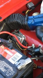
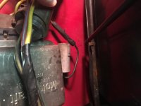
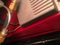
On the right fender is blk/red blk/yellow
The large Black w/red is your main power to the cabin. Powers up literally everything and allows the current from the alternator to charge the battery.
The large Black w/yellow is the alternator charge wire. With a normal charging system on a Bronco, both of these have to be connected for things to work normally.
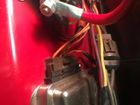
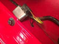
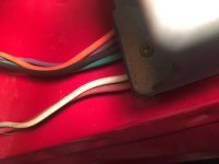
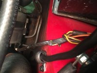
out of the voltage regulator is brown, yellow x2, red, and white/blk. No matter how we wire it I have nothing at the switch and there is a total loss of power as if there is a bad ground.
Just so you know, nothing at the voltage regulator (or alternator for that matter) can stop power to the rest of the truck. So even if this was wired incorrectly, it's not the main problem.
But I see one issue, and that's the colors of the wires. They indicate to me that a replacement 4-wire connector has been installed. Not a problem, but the wires get confusing because of it.
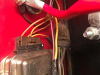
For proper orientation of the wires, look for the markings on the connector and/or regulator. You should be able to find an "F S A I" mark on the four contact points of the regulator. ON BRONCOS, ONLY THREE ARE USED.
That last point confuses even a lot of Ford knowledgeable people.
The first position is the "F" (or Field) wire. It's usually Orange, so your Brown wire is likely it's substitute. This goes directly to the F post on the back of the alternator and nowhere else.
The next is the "S" (or switched) wire. Normally it stands for "stator" but in Ford vehicles with an ammeter gauge instead of an indicator lamp on the dash, we refer to it as simply switched, because it comes from the ignition switch directly. Standard color is Green w/red stripe.
You need to find out which of your wires has got 12v with the key in RUN (not in ACC) and use that in this position.
Next us the "A" wire (or "always hot"
")
) wire. Originally stands for "armature" on indicator vehicles, but we say "always" for lack of a better term because it has power all the time. This is where the two Yellow wires connect.
One yellow is to the battery positive (usually spliced into the large Black w/red wire) and the other to a radio noise suppressor/capacitor typically bolted to one of the regulator mounting bolts.
The fourth position marked "I" is not used. So you should only connect three of the four wires to something. Best to remove the fourth so it doesn't cause any mischief.
This should get your alternator working unless there are other connection issues.
I will change the neutral safety switch in case that is causing the problem.
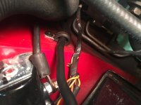
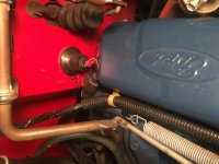
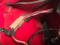
It can, but don't change it yet. You can easily test it, or even bypass it easily. Your '77 harness will have a square 4-wire connector behind the engine at the firewall with two Red w/black wires, and two Red w/blue wires.
The Red w/blue are your NSS wires, and make or break the connection to the starter relay's "S" post.
The Black w/red wires are your backup lamp wires.
You can disconnect the connector, jumper a wire between the two Red w/blue wires and that will literally connect your ignition switch to the starter relay on the fender and allow you to start the vehicle with the key no matter what gear you're in. So be careful!
Is there another fuseable link in the harness somewhere I do not readily see or what else could be causing loss of power?
Normally not that would have any effect on what you're experiencing, but that Black w/red wire at the starter relay has one that could have blown. You will need to inspect it to be sure.
Only three things can kill power to the whole vehicle.
1. The Black (or Black w/red in your case) 10ga battery wire at the starter relay. Could be a problem with the wire, or could be a problem with the fusible link.
2. There is a connector on that same wire just behind the ammeter in your instrument cluster that could be broken, rusted or simply disconnected. Before you do anything else then, make sure this connector is in good shape.
3. Battery cables. Either positive or negative could have failed internally even if they look perfectly fine. Once you've taken care of all the other things, if it still gets no power anywhere, check or replace your cables.
I would like a picture of a 77 wiring from battery, alternator, voltage regulator back to the firewall if some one has this I would appreciate it.
See if some of what I was writing can get you there until someone has a pic for you.
I can't figure out what the difference is where it shows the wiring going to a solid black circle and then a non colored circle. I know solid vs clear circle means something but there is no legend, can anyone help?
Not sure myself. Would have to see it in context.
Good luck!
Paul