• Welcome to ClassicBroncos! - You are currently viewing the forums as a GUEST. To take advantage of all the site features, please take a moment to register. It's fast, simple and absolutely free. So please join our community today!
    If you have problems registering or can't log into your account, please contact Admin.

Brake bleeding / dummy light update

DirtDonk

Contributor
Bronco Guru
Joined
Nov 3, 2003
Messages
49,365
Somebody recently (I think it was James Roney?) gave a good description on how the different switches work.
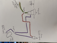
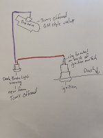
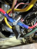
But with the modern valve with a single wire switch going to what was originally a two wire set up in the bronco, you simply twist the two wires from the bronco to the one wire on the switch. It’s not a one wire to one wire simple connection.

As you’re saying the lamp tests itself every time you turn the key to start. It literally lights as long as the key is in the start position though. It doesn’t flash like a blinker, it stays lit until you release the key.

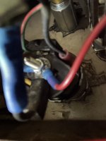
To do this the ignition switch must be mounted to the dash so that it has a ground path through its body. Which means the battery has to have a body ground and the dash can’t be all painted up and powder coated or rusty. All those things get in the way of a good ground connection.
The test wire, or prove out circuit, is simply a ground for the switch in the start position only.

Beyond those basics, I literally have to study the wiring diagrams for half an hour every time I’m gonna work on one of those circuits just to make sure that I’m seeing it clearly in my head.
So you’re certainly not alone in head scratching with the brake warning light circuit.
 
OP
OP
C

CopperBronco

Jr. Member
Joined
Aug 13, 2021
Messages
388
So I didn’t wire it up wrong is what I’m hearing… so that’s good. The warning switch lamp didn’t come with a ground wire on it, maybe I’ll add one somehow. Everything else grounds fine from my dash I believe…. How do I test with a multimeter or test light if the ignition switch is grounding properly? Is there a simple way?
 

DirtDonk

Contributor
Bronco Guru
Joined
Nov 3, 2003
Messages
49,365
No, I guess I was sideways in my wording, but I was trying to say that no it doesn’t sound correct to me.
Where is the second wire? Is this an original factory wiring harness or a replacement?
Is there a wire to a small terminal on the side of the ignition switch? Without that you will never get the light to test in the start position.

You do not need to add a ground to a switch made of plastic that has only one contact. If it is a grounding switch, which in this case I think it is, that grounds through the proportioning/combination valve to the frame.
If that’s the case then making sure that the mounting surface and bolt threads are clean would be a good idea.

I’ll try to check out your wiring diagram later, but if it’s a stock wiring diagram, or even one for a later bronco, then it’s not quite exactly the same thing as what you have now with an aftermarket combination valve and switch that is probably based on its GM counterpart.
The original had two wires, so if yours only has one wire that it’s not gonna follow the same parameters.
Still seems to me like you’re missing at least one wire.
 
OP
OP
C

CopperBronco

Jr. Member
Joined
Aug 13, 2021
Messages
388
Hi Paul, maybe this is more clear, see attached. My 66 harness is some sort of replacement harness, but it’s in rough shape. I bypassed it entirely with all new wiring. See attached photo.

I took one of my multimeter leads connected to the brake warning light electrical connector on the back of it and connected it to a ground bolt on the dash with the other lead and the switch lit up while key was in on position. So I have power, but it’s not grounding, right?

Does anything else ground from ignition switch? Because everything else in my Bronco works fine… which leads me to believe other things wouldn’t work if grounding was an issue. I do have multiple ring terminals on the back of that thread on the back of the ignition switch. Maybe it’s not working with 3 stacked ring terminals and losing its ground? Just spitballing ideas here.

I might look into adding a dedicated ground wire to the light warning switch somehow… not sure how to go about that. Can I splice into existing wires and add a dash ground wire? Or solder a ring terminal with a ground wire to back or the brake warning light?
 

Attachments

  • 1D5082CE-4239-41A8-9561-111ABB10D1A1.jpeg
    1D5082CE-4239-41A8-9561-111ABB10D1A1.jpeg
    113 KB · Views: 62
OP
OP
C

CopperBronco

Jr. Member
Joined
Aug 13, 2021
Messages
388
Doing my own research here. Either I need to take my red wire in photo above and add a spade terminal and connect to the ignition switch terminal on the side of the ignition connection/pigtail, see first photo of where it goes...

But from looking at all 3 of these diagrams, the ones from the Seabiscuit/tripod site, or Painless' booklet (I have a new harness not installed yet, one day I'll find time to rewire the old beast...). It looks like I need to splice my purple wire at the prop valve switch and run one wire to the lamp, and one wire to the ignition, meanwhile the red wire just needs an ignition hot connection, Painless' guide recommends at the IVR input wire to splice. But can't I just get the same from the auxiliary power threaded/bolt on back of ignition?

Just want to make sure I'm thinking straight here.
 

Attachments

  • brake imbalance.jpg
    brake imbalance.jpg
    33.9 KB · Views: 71
  • tempImagePeA8cm.png
    tempImagePeA8cm.png
    1 MB · Views: 67
  • tempImage94Jo7M.png
    tempImage94Jo7M.png
    1.1 MB · Views: 44
OP
OP
C

CopperBronco

Jr. Member
Joined
Aug 13, 2021
Messages
388
Yeah, I think it goes like this, right? See diagram I drew up/modified from before... do I have this right? My '68 Bronco service manual also shows it differently... where the purple wire splices together at the ignition connection point on the back of the ignition switch, (also attached, it's #977 in the diagram). I'm thinking I have a wiring problem right now, need to go splice the purple wire and hook to ignition switch, and re-test, then if that doesn't work, check for ground issues. Please correct me if I'm off here. I'm hoping it's okay to power off the ignition auxiliary power for the light/lamp, most diagrams show it spliced into the hot side of the starter solenoid wire going into ignition, or the back of the IVR. But all 3 of these are 12 volt powered, correct? It shouldn't matter is my thought.
 

Attachments

  • tempImageNUvG7y.png
    tempImageNUvG7y.png
    869.6 KB · Views: 60
  • tempImageuyErKh.png
    tempImageuyErKh.png
    1.2 MB · Views: 60

DirtDonk

Contributor
Bronco Guru
Joined
Nov 3, 2003
Messages
49,365
Sorry copper, I haven’t had time to look through it. But I had forgotten you had a 66, which not only had some unusual wiring in some cases anyway, but would also not have come with a brake warning light because it only had a single reservoir master cylinder.

A few things going on here though.
With all the replacement stuff and the fact that it’s a 66, you’re starting from scratch.
For now we will assume that it’s not an original 66 ignition switch, but even then it may have come with a prove out connector on the side. That prove out connector is where it grounds. As mentioned earlier that grounds the switch through the dashboard, but only in the start position. As a way to test the bulb every time you start.

In your earlier diagram you have 12v power from the accessory post of the ignition switch to one side of the imbalance switch. So every time the key is either on or in ACC, you have 12 V going to one side of the switch. If the other side of the switch grounds then you should get the light.

But something else is unusual here. Either Toms now has a modern combination valve with an early style Ford switch, or you have a mismatch switch.
All the ones I’ve seen for the last 30 years have only a single terminal for a wire. Only before switch had to post for the wires, but that would never threatened to a gym style combo valve.
Again, maybe Toms has had their own made so that the old switch fits the new valve. I just don’t know.
Any chance we can see some pictures?
 

DirtDonk

Contributor
Bronco Guru
Joined
Nov 3, 2003
Messages
49,365
Dammit Jim… (said in his best Dr. McCoy voice)
I couldn’t keep the picture and the words straight in my head so I miss spoke about the switch and the valve. Working at the restaurant tonight so my mind is mixed up between food and Broncos.🙄

Anyway, I see the two poles is the light and the single pole is the switch. So it is a standard late model GM switch unlike what I was saying above. So ignore that and I’ll actually go back and correct it when I get back home.

Basically though, you will never have the light come on as a test the way that it is currently wired. It will only come on if the switch goes to ground.
 
OP
OP
C

CopperBronco

Jr. Member
Joined
Aug 13, 2021
Messages
388
All my parts are newer, as in not original 66 parts… my ignition, prop valve and brake light switch are new from Tom’s off-road. I will post some pics shortly. Is the short answer that I need to wire it up the way I the factory diagram? I was hoping for a simpler solve. And yes I’m starting from scratch since my Bronco never had one. You are right that my light only works right now when I ground it with my multimeter or test light. I do have a connector on back of ignition switch for the dual brake warning light, I didn’t realize what that was for until I dug up these diagrams tonight.
 
OP
OP
C

CopperBronco

Jr. Member
Joined
Aug 13, 2021
Messages
388
Photos… the first one the black wire top right turns into the purple white brake warning wire… (looks like PO had one at one point, but wire disappears into loom somewhere). Regardless I can remove/replace. The red wire in photo 1 is my power wire to the brake warning light lamp, I need to change this to a different 12v source I believe. LMK if you have any thoughts… I hope to rewire tomorrow 🤞.
 

Attachments

  • 056CDF0B-3CC7-4BD7-8D35-63CCA1786D12.jpeg
    056CDF0B-3CC7-4BD7-8D35-63CCA1786D12.jpeg
    217.3 KB · Views: 64
  • 2D865950-DB8D-41C3-BE93-5469F87982C3.jpeg
    2D865950-DB8D-41C3-BE93-5469F87982C3.jpeg
    250.1 KB · Views: 37
  • 5558E6B1-AFB3-41B5-8812-673F60AB4472.jpeg
    5558E6B1-AFB3-41B5-8812-673F60AB4472.jpeg
    260.7 KB · Views: 58
  • CBCF86FF-383B-4252-B6B6-4D0E71E67E58.jpeg
    CBCF86FF-383B-4252-B6B6-4D0E71E67E58.jpeg
    148.2 KB · Views: 61
  • 65E078B5-C069-4DBB-8B93-1ABDE6C1E258.jpeg
    65E078B5-C069-4DBB-8B93-1ABDE6C1E258.jpeg
    122.1 KB · Views: 61

Jdgephar

Bronco Guru
Joined
Sep 25, 2012
Messages
1,384
I think you're good with your hand drawn wiring. My only question is when does the center post on the ignition have 12V, in start and run? If so, you should be all set. The only other thing to check is if the proportion valve is properly grounded so the light will turn on, and if the key switch has ground in start. You can test the light with piece of wire on the ground wire (your purple wire) temporarily to a chassis ground if you want to with the key in run.

Sent from my SM-G981U using Tapatalk
 
OP
OP
C

CopperBronco

Jr. Member
Joined
Aug 13, 2021
Messages
388
I think you're good with your hand drawn wiring. My only question is when does the center post on the ignition have 12V, in start and run? If so, you should be all set. The only other thing to check is if the proportion valve is properly grounded so the light will turn on, and if the key switch has ground in start. You can test the light with piece of wire on the ground wire (your purple wire) temporarily to a chassis ground if you want to with the key in run.

Sent from my SM-G981U using Tapatalk
So the prop valve needs to ground to body as well? I thought only ignition switch had to ground to dash?
 

DirtDonk

Contributor
Bronco Guru
Joined
Nov 3, 2003
Messages
49,365
What we’re describing is kind of a two-way circuit. Or maybe a dual circuit would be a better term. Or a “reversible “ circuit maybe?🙄
On the one hand the ignition switch grounds one branch of the circuit as a test. On the other the switch grounds at the frame or body to turn on the light if there is an imbalance in the hydraulic system.
Perhaps it can ground through the metal tubing, or the mounting bracket if there is one.
Does not have to ground to the body specifically. Can ground to the frame or the body. A ground is a ground because they all end up back at the battery’s negative side.

But with only one wire coming from the ignition switch it has to be 12 V or it will not work both ways. You can either have a test circuit, or you can have a working circuit. But not both. For that to happen the way you want, you need two distinct grounds and one power source that’s hot anytime the key is on or in ACC positions.

The way you are getting 12V from the center post of the ignition switch will never allow it to test. The accessory section is disabled when the key is turned to start.
The wire that it is connected to from the factory is the green with red stripe wire. That comes out of the ignition switch and goes to multiple accessories in later Broncos, but only the voltage regulator on the earlier years.
Only the Green w/red and Red w/green wires are hot in ACC and ON.

So tap into the Green w/red stripe wire for your power, keep the purple on that side terminal of the ignition switch, run them both out to the switch on the valve, and twist the three wires together. Yep, twist the three wires together.

This way you have power to the lamp but no ground because the lamp is not grounded through its housing. If the switch on the valve is tripped it goes to ground and the light comes on. If the key is turned to start at grounds the other wire and the light comes on.
 
OP
OP
C

CopperBronco

Jr. Member
Joined
Aug 13, 2021
Messages
388
What we’re describing is kind of a two-way circuit. Or maybe a dual circuit would be a better term. Or a “reversible “ circuit maybe?🙄
On the one hand the ignition switch grounds one branch of the circuit as a test. On the other the switch grounds at the frame or body to turn on the light if there is an imbalance in the hydraulic system.
Perhaps it can ground through the metal tubing, or the mounting bracket if there is one.
Does not have to ground to the body specifically. Can ground to the frame or the body. A ground is a ground because they all end up back at the battery’s negative side.

But with only one wire coming from the ignition switch it has to be 12 V or it will not work both ways. You can either have a test circuit, or you can have a working circuit. But not both. For that to happen the way you want, you need two distinct grounds and one power source that’s hot anytime the key is on or in ACC positions.

The way you are getting 12V from the center post of the ignition switch will never allow it to test. The accessory section is disabled when the key is turned to start.
The wire that it is connected to from the factory is the green with red stripe wire. That comes out of the ignition switch and goes to multiple accessories in later Broncos, but only the voltage regulator on the earlier years.
Only the Green w/red and Red w/green wires are hot in ACC and ON.

So tap into the Green w/red stripe wire for your power, keep the purple on that side terminal of the ignition switch, run them both out to the switch on the valve, and twist the three wires together. Yep, twist the three wires together.

This way you have power to the lamp but no ground because the lamp is not grounded through its housing. If the switch on the valve is tripped it goes to ground and the light comes on. If the key is turned to start at grounds the other wire and the light comes on.
Alright, I'll twist the three wires at the prop valve, the two purple and one black from the switch and put into a closed end connector and then splice my brake warning lamp red wire into the green/red coming off the ignition. Curious how you guys splice into existing wires? A 3 way Y connector terminal, posi-taps? or good old remove about 1.5" plastic casing around existing wire and wrap new wire around it, and then seal it up with heat shrink and electrical tape? As for grounding the prop valve... do you think I could just scrape the bottom of the fender where the prop valve bolts attach to the fenders and tighten down with some star washers after cleaning off bottom of fender area? And how do I use my multimeter to validate I have a good ground from prop valve to body? Would it be with Key turned to on position, I put my black lead on the prop valve bolt, and the red lead on my positive of battery and see if I'm running under 5 ohms resistance? or could I just test ground from back of brake warning light lamp connector with red lead, and put the black lead on my dash ground bolts? I feel like I need a master tutorial somewhere on all major Bronco automotive electrical concepts. Definition for test circuits, double circuits, relays, etc... :) Please point me to it if it already exists.
 
OP
OP
C

CopperBronco

Jr. Member
Joined
Aug 13, 2021
Messages
388
So I installed it all like the below diagram, + the photos so you can see. I used a Y connector to splice into the green/red ignition wire, bronco starts up fine and with Key in On position I get 11.4 volts through it approximately, Bronco starts nice and smooth. The brake warning lamp only turns on when I ground it to the dash with my multi-meter, but it doesn't turn on even briefly when I start the Bronco. Any thoughts? The messy photo of my ignition switch wiring, you can see the blurred purple wire coming from the prop valve switch going into side of ignition terminal, then the blue Y connector behind the purple wire is where I spliced in the red power wire from the brake warning lamp/light into the green/red ignition 12V hot wire. I also cleaned up the bolt area underneath my fender attaching my prop valve to my fender. I scraped it clean and added a star washer to it and tighten back down, so ideally the prop valve is grounded to the body/fender now. Any thoughts?
 

Attachments

  • tempImagebdmLSS.png
    tempImagebdmLSS.png
    1.2 MB · Views: 51
  • tempImageHmPVnb.png
    tempImageHmPVnb.png
    1.3 MB · Views: 45
  • tempImagefVKSJL.png
    tempImagefVKSJL.png
    1.4 MB · Views: 66
  • tempImage4Bg2tt.png
    tempImage4Bg2tt.png
    912.1 KB · Views: 70
Last edited:

DirtDonk

Contributor
Bronco Guru
Joined
Nov 3, 2003
Messages
49,365
You might double check that the side terminal on the ignition switch is actually grounding when it’s turned to start.
Unplug the purple wire from the switch (and the red w/blue wire from the starter relay) and use your ohm-meter to see if it’s grounding sufficiently to the dash.

Based on your wiring diagram it looks correct to me. But I’d still feel better if somebody who was intimately familiar with that circuit would chime in and give their two cents of thoughts on the subject.
 

DirtDonk

Contributor
Bronco Guru
Joined
Nov 3, 2003
Messages
49,365
Here’s another test. Disconnect the purple wire from the side of the ignition switch and ground it. That would act just like it should when the switch grounds to the dashboard.
If it doesn’t light up at that point then we have to go back to the drawing board. But at least it’ll tell you something.
 

Steve83

Bronco Guru
Joined
Jul 16, 2003
Messages
9,126
Loc.
Memphis, TN, USA, Earth, Milky Way
What we’re describing is kind of a two-way circuit. Or maybe a dual circuit would be a better term. Or a “reversible “ circuit maybe?🙄
On the one hand the ignition switch grounds one branch of the circuit as a test. On the other the switch grounds at the frame or body to turn on the light if there is an imbalance in the hydraulic system.
That's called "parallel" because the current can flow through either branch. Only bi-directional DC motors (like PW/PL/PAnt) use polarity-reversing circuits.
 
OP
OP
C

CopperBronco

Jr. Member
Joined
Aug 13, 2021
Messages
388
Here’s another test. Disconnect the purple wire from the side of the ignition switch and ground it. That would act just like it should when the switch grounds to the dashboard.
If it doesn’t light up at that point then we have to go back to the drawing board. But at least it’ll tell you something.
You're spot on, I pull that purple wire off the ignition switch and touch it to my dash ground bolts and it lights up while the Key is in the "on" position, is that how it's supposed to behave? Stay on while in the "On" position, and flash when you twist to start? So my guess is I need to pull the ignition switch again and sand/clean the back of the dash some. It's been done before I can see where they went at it already, so I thought it might be good. It could also mean my prop valve isn't ground too though, right? So maybe the star washer on the bottom of the fender needs work... not sure how well I can clean under the prop valve without disconnecting everything to get room underneath it.... ugh... hopefully just the dash. Thanks again for everything, super helpful! LMK if you have any other ideas besides cleaning up the dash contact area.
 
Top