• Welcome to ClassicBroncos! - You are currently viewing the forums as a GUEST. To take advantage of all the site features, please take a moment to register. It's fast, simple and absolutely free. So please join our community today!
    If you have problems registering or can't log into your account, please contact Admin.

Burning up Voltage Regulators

Annapolis76EB

Sr. Member
Joined
Apr 3, 2009
Messages
565
Loc.
Annapolis, MD
For some reason I hink I keep burning up voltage regulators. I think it might have to do with grounding. I was driving last night and my headlights started flashing on and off. I am going to clean my main battery ground up at the block and see if that helps. Also, I just replaced my alternator (1g for 1g) and wondered if it should be grounded somewhere as well. Should I run a ground strap from one of the posts on the rear to somewhere on the engine? Thanks for the help.
 

Viperwolf1

Contributor
electron whisperer
Joined
Aug 23, 2007
Messages
24,335
The voltage regulator should have a ground wire attached to one of the mounting screws. That wire goes to the alt harness. At the alt, the wire terminates at the harness mounting tab and gets attached to one of the ground posts on the alt.

A heavy ground wire between the alt, body and battery is always a good thing to add.
 

Attachments

  • alt-reg.jpg
    alt-reg.jpg
    37 KB · Views: 78
OP
OP
Annapolis76EB

Annapolis76EB

Sr. Member
Joined
Apr 3, 2009
Messages
565
Loc.
Annapolis, MD
Currently I dont have the ground wire from the mounting screw. There was a wire previously going from the screw that tied into the main battery ground at a kill switch that is installed. SHould I just run this wire back to the ground/kill switch or does it need to go to the alternator? One other question, what voltages should I be getting at my VR wires? Should I have full voltage on the F and S? Is it different when keyed? Thanks for all the help Phil. You are always a life saver.
 
OP
OP
Annapolis76EB

Annapolis76EB

Sr. Member
Joined
Apr 3, 2009
Messages
565
Loc.
Annapolis, MD
Right now I have the same voltage at the black and white wires at the VR harness with the key on or off. Shouldnt one of these be dead with the key off? Bad ignition switch?
 

Viperwolf1

Contributor
electron whisperer
Joined
Aug 23, 2007
Messages
24,335
You need the ground tying the reg to the alt. Don't know why it would be tied to a kill switch unless you were trying to kill the regulator.

"F" voltage is dependant on "A" voltage and "S" voltage. If battery voltage is low and "S" is 12V, "F" voltage goes up.
"S" voltage is about 12V with key ON only. Key OFF is 0V.
"A" voltage is always full battery voltage.

Don't know what black and white wires are.
 

DirtDonk

Contributor
Bronco Guru
Joined
Nov 3, 2003
Messages
47,915
Is this on a Bronco Annapolis? Or a Ford pickup? Either way, what year?
What position is the Black and white wire in? Is it White with a black stripe by any chance?

Reason I ask is that only Ford trucks without an ammeter used the White w/black "S" wire (stator) on a voltage regulator. Otherwise, if it's a later model Bronco with an electric choke, the Stator wire went from the alternator's "STA" post to the choke directly.
On an EB, that "S" terminal on the regulator should be populated by a Green w/red wire that is only on with the key, as Viper said.

Got pics?

Paul
 
OP
OP
Annapolis76EB

Annapolis76EB

Sr. Member
Joined
Apr 3, 2009
Messages
565
Loc.
Annapolis, MD
The kill switch is just a hidden switch under the fender that cuts off the ground connection between the engine and battery. A theft detterrent kind of thig. The VR was grounded to this originally, but never to the alternator. Will this fry the VR being hooked up this way?

On the wires (my colors were wrong originally due to splices) , from the VR I have orange going to field on the alternator and green goes off somewhere to the ignition. The yellow goes through a fusable link to the solenoid. Does this sound right? Now I should just run a ground from the VR to the grd post on the alt?

Coming off of the alt I have the orange to the VR on field and black/yellow wire that goes off into a bundle towards the cab. Thanks guys
 
OP
OP
Annapolis76EB

Annapolis76EB

Sr. Member
Joined
Apr 3, 2009
Messages
565
Loc.
Annapolis, MD
Paul-It is a 76 Bronco. The confusion with the wires is because the actual pigtail that plugs into the VR must be aftermarket and had Y, B and W colored wires, but these are spliced into the normal colors.

I wired everything up as Phil's diagram showed. I know have the ground going from the VR mounting bolt to the grd post on the alt. Hopefully this will solve my problem burning up VRs. Just out of curiosity, wouldn't the VR ground to the body when it is mounted to the inner fender well? Would not having the ground between the VR and alt cause VRs to fry out? Thanks guys.
 

DirtDonk

Contributor
Bronco Guru
Joined
Nov 3, 2003
Messages
47,915
Yes, they ground to the body. But there are two factors at work here I think.
One is that the Bronco bodies don't exactly make the worlds best grounding surfaces.
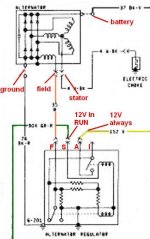
And two, there may be another reason that you want the regulator grounded directly to the alternator.
I'm not really sure about that, but Viper, Raymond, or Steve83 might know the theory behind it. It may simply be that this is the best way to keep the ground as reliable as possible. And since the two items are so intimately involved with each other's functions, they just like them to be grounded together.

As to why you're blowing regulators, the only thing I can think of is to go back to #1 and say that, perhaps, your fender just ain't grounded like it used to be. Powering up a regulator without it being grounded is generally considered the quickest way to need a new one.
There may be other things that can blow a regulator, but I don't know what they are.

And along that line of thought, what is the condition of your ground cables? Do you have the main one to the engine block (not a head or manifold bolt) AND a good solid one to the body? There really should be more of course, and all modern vehicles do have more, but those two are the grounds in their most basic form. In reality, the entire truck should be interconnected with grounds. Whether in the form of wires, cables, straps or direct connections, the whole shebang, body, engine, frame, needs a good connection.

Check that aspect out too, and see if you're missing something. The most common thing to found lacking is the battery-to-body ground. The factory had it in-line with the main cable to the engine, using one lead, so when negative battery cables are changed out, the body ground connection often doesn't get re-connected.

Paul
 

DirtDonk

Contributor
Bronco Guru
Joined
Nov 3, 2003
Messages
47,915
...Either way, what year?

Ok, so that was one of those "duh" questions, given your screen name, but my mind was already on wiring possibilities.

But yeah, I choked on that one. Hah!
Wouldn't be the first time.

Paul
 

DirtDonk

Contributor
Bronco Guru
Joined
Nov 3, 2003
Messages
47,915
Oh, and when checking those wires at the regulator, especially if they've got splices in them from some time back, verify voltages.
I think it was mentioned already, but you want FULL BATTERY VOLTAGE at the wire attached to the original Yellow (A) wire. Key on or off, doesn't matter.
And you want the same full battery voltage at the "S" wire connected to the Green w/red wire from the original harness.
Any variation on that theme, by more than, say, 2 tenths of a volt, is grounds (no pun intended) for re-doing that circuit. So double check those voltages.

And the Yellow wire with the fusible link that you can see at the starter relay is more likely to be for (or should be for) the horn relay on the inner fender.

Where is your regulator? Still on the fender, or over on the firewall above the heater hoses?

I'm curious, and this is all important stuff to know, but remembering this stuff late is also just a good excuse to get my post-whoring self closer to that 10,000 mark!

Paul
 
OP
OP
Annapolis76EB

Annapolis76EB

Sr. Member
Joined
Apr 3, 2009
Messages
565
Loc.
Annapolis, MD
Thanks Paul. I think I will need to add the batt to body ground. Currently my batt ground goes from the battery to a switch mounted on the inner fender (see pic) and from there to the engine block. Coming off the engine block ground connection is another ground strap that goes to the frame. On the back of the head right below the intake manifols (I think) is a ground strap that goes to the body. Any recommendation on where to add the batt/body ground? Thanks.
 

Attachments

  • photo.jpg
    photo.jpg
    86.7 KB · Views: 20
OP
OP
Annapolis76EB

Annapolis76EB

Sr. Member
Joined
Apr 3, 2009
Messages
565
Loc.
Annapolis, MD
VR is on the fenderwell still and I do have more than a tenth of a volt drop between the yellow and green. Does the green wire run to the ignition switch through the megafuse on the fenderwell? Everything else is as you described.
 

Viperwolf1

Contributor
electron whisperer
Joined
Aug 23, 2007
Messages
24,335
The kill switch is just a hidden switch under the fender that cuts off the ground connection between the engine and battery. A theft detterrent kind of thig. The VR was grounded to this originally, but never to the alternator. Will this fry the VR being hooked up this way?

On the wires (my colors were wrong originally due to splices) , from the VR I have orange going to field on the alternator and green goes off somewhere to the ignition. The yellow goes through a fusable link to the solenoid. Does this sound right? Now I should just run a ground from the VR to the grd post on the alt?

Coming off of the alt I have the orange to the VR on field and black/yellow wire that goes off into a bundle towards the cab. Thanks guys

That backhoe device (ground opener, get it?) could very well be the cause of your regulator troubles, depending on how it was attached. The regulator will fry quickly if it isn't grounded. It is (should be) grounded at the fender but it's better to ground it at the alternator. The theory behind it is: the negative cable from the battery to the engine has to be at least good enough to pass charging current if it passes enough current to run the starter. The body ground is not as good. This places the two grounds at slightly different potentials (voltage). The neg post of the battery has the most negative potential in the system. The pos post has the most positive potential. A body ground has slightly more positive (less negative=more positive) potential than the neg post. Since the VR has to measure actual charging voltage to determine correct field voltage, it's best to measure the voltage that the battery sees (that's the voltage directly from the alt). A not-so-good ground at the VR would cause the charging voltage to be higher than required.

Your wiring sounds good. Ground the VR to the alt.
 

Viperwolf1

Contributor
electron whisperer
Joined
Aug 23, 2007
Messages
24,335
VR is on the fenderwell still and I do have more than a tenth of a volt drop between the yellow and green. Does the green wire run to the ignition switch through the megafuse on the fenderwell? Everything else is as you described.

The green wire does go through the ign sw and will drop some voltage (become less positive). It's not that critical. I wouldn't worry about it. The yellow wire voltage is critical.
 
OP
OP
Annapolis76EB

Annapolis76EB

Sr. Member
Joined
Apr 3, 2009
Messages
565
Loc.
Annapolis, MD
Thanks Phil. Do you suggest I remove my "backhoe deice" (funny) or do you think having the VR to alt ground I will be OK now? The PO put that on for security since he worked in NYC. No need for it around here. Also, should I try to run an inline ground to the body from the batt? Maybe add a wire at the negative battery terminal and run it directly to the body? I will do anything at this point to quit frying VRs and one coil as well. Thanks guys.
 

Viperwolf1

Contributor
electron whisperer
Joined
Aug 23, 2007
Messages
24,335
Thanks Phil. Do you suggest I remove my "backhoe deice" (funny) or do you think having the VR to alt ground I will be OK now? The PO put that on for security since he worked in NYC. No need for it around here. Also, should I try to run an inline ground to the body from the batt? Maybe add a wire at the negative battery terminal and run it directly to the body? I will do anything at this point to quit frying VRs and one coil as well. Thanks guys.

It's up to you. If you want to keep it you need to make sure all the grounds are going through it. In other words, no other grounds coming off the battery terminal. That will make it as effective as removing the battery and keep everything from frying.

A better body ground is always a good thing. You could just attach a cable from the block (where the ground cable is now) to the inner fender.
 

DirtDonk

Contributor
Bronco Guru
Joined
Nov 3, 2003
Messages
47,915
And when he said "not that critical" about the "S" wire, I think he meant that a couple of tenths isn't anything to worry about. But if there's enough difference, then you should still "worry" about it.
Is that right Phil? Or do you feel that you can get away with a lot more than I usually tell people?

Paul
 

Viperwolf1

Contributor
electron whisperer
Joined
Aug 23, 2007
Messages
24,335
And when he said "not that critical" about the "S" wire, I think he meant that a couple of tenths isn't anything to worry about. But if there's enough difference, then you should still "worry" about it.
Is that right Phil? Or do you feel that you can get away with a lot more than I usually tell people?

Paul

Yep, a few tenths is no big deal. I'd look at fixing it if it was a whole volt different. That current just turns the VR on.
 

DirtDonk

Contributor
Bronco Guru
Joined
Nov 3, 2003
Messages
47,915
...That current just turns the VR on.

Hmmm, I thought it was also a "comparator" circuit so the regulator knows the voltage at the battery (Yellow wire) and what's being seen at the other end of the system at the accessories or coming off the alternator (Green w/red wire).

I've often wondered why Ford chose to change the orientation of the wires when used with a dash indicator lamp, vs an ammeter.
You're into the deep dark knowledge end of this, or electrical theory as it applies to the the real world at least. Correct?
Do you know the logic behind the swap? Was it something to do with the original function of the dash light in the "I" circuit?

With a light, the Green w/red wire does apply current to the "on-switch" through the "I" terminal. With an ammeter though, it's on the "S" terminal. Which, what, kind of throws the switch from the backside, so to speak? Without the need for some sort of report through the "I" terminal?

So, is there even a comparison going on inside then? Or does the regulator simply "know" what to tell the alternator to do, when it senses voltage outside of certain parameters?
I wouldn't be surprised of course, I just thought there was some comparing going on between the two.

Probably just over-thinking things, as usual, but I always wondered why the change in wiring schemes between a light or an ammeter equipped vehicle.

Paul
 
Top