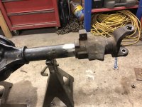
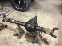
Those that have cut down the 78-79 did it need caster correction ?
Community
Message Forum
Photo Gallery
Event Calendar
Book Reviews
Bronco Wallpaper
Bronco FAQ
Link Back to CB!
Photo Gallery
Event Calendar
Book Reviews
Bronco Wallpaper
Bronco FAQ
Link Back to CB!
Buy / Sell


Bronco Tech
3 Arm Wiper Setup
Fix Motor Mount
Roll Cage Braces
Throttle Body 65mm
Wheel Alignment
Heat Riser Replacement
Vent Window Repair
Center Console Mount
Straighten Bumper
Ford 6R80 6 spd
More Tech...
Fix Motor Mount
Roll Cage Braces
Throttle Body 65mm
Wheel Alignment
Heat Riser Replacement
Vent Window Repair
Center Console Mount
Straighten Bumper
Ford 6R80 6 spd
More Tech...

Install the app
-
Welcome to ClassicBroncos! - You are currently viewing the forums as a GUEST. To take advantage of all the site features, please take a moment to register. It's fast, simple and absolutely free. So please join our community today!If you have problems registering or can't log into your account, please contact Admin.
You are using an out of date browser. It may not display this or other websites correctly.
You should upgrade or use an alternative browser.
You should upgrade or use an alternative browser.
Dana 44 high pinion narrow and install
- Thread starter stupidboy
- Start date
Let me ask the question differently.
If I use the 79 hp 44 and cut 6” off the right side, will I need to cut the left side loose also to get the right pinion angle and still get the proper caster ???
I got busy today and got it cut.
If I use the 79 hp 44 and cut 6” off the right side, will I need to cut the left side loose also to get the right pinion angle and still get the proper caster ???
I got busy today and got it cut.
Attachments
Thanks James, I appreciate all the knowledge you’re sharing with me.Let me answer the question EXACTLY the same. There are LOTS of people that just shorten one side. There are LOTS of people that do not perform the caster correction. There are LOTS of people that complain when their lifted Bronco will not go down the road straight.
If you are looking for a single answer, there isn't one. There is just experience based on the prioritization of needs. Once YOU prioritize your needs, the answer will bubble to the top. So let's list the constraints:
1. Proper steering geometry and caster. The proper caster for a 93 inch wheelbase live axle, power steering vehicle on 35's is 6 degrees positive. If you want to go down the road straight, and not wander then it's 6 degrees. If you are on 33's, the answer is 7 degrees. If you want it to dart around and steer like your mountain bike...set it at 3 degrees, and hold on.
2. Proper u-joint angle. The proper u-joint angle for the axle end of a Double Cardan Bronco driveshaft is 0.5 degrees. That means that the pinion should point directly at the transfer case, and the angle at the u-joint should be 0.5. If the driveshaft is pointing down 10 degrees, then the pinion should point up 9.5 degrees. It's simple. If the driveshaft u-joint has a kink in it, it will wear prematurely, and it will vibrate at high speed. It will also be weaker but any angle below 10 degrees is not significant. At 33 degrees, the u-joint is about 1/2 strength.
3. Proper differential clearance. The front axle housing needs a place to go when you compress the suspension. A Bronco with a High Pinion 44 that is not lifted will have clearance issues with the front driveshaft yoke and the exhaust. And it will have clearance issues with 351W truck pan. This is the reason for shortening the short side. 5/8 inches may not seem like much, but it matters A LOT. If you run 6 inches of lift, and you have good bump stops, then there is no issue with running the short side "long."
Since you did the work, and you obviously have decent skills, I will tell you what I would do. I would 100% absolutely, positively and for sure pull the driver's tube. And I would shorten it 5/8 inches. And I would mount it into your A4F long arms, with whatever bushings you have on hand. Set the suspension height and measure the caster. Then set the caster as close to 6 as you can get it. Then I would point the pinion at the transfer case and weld it all.
Work looks good. It's going to turn out great.
I hope you won’t mind if I run across some more questions.
Broncobowsher
Total hack
- Joined
- Jun 4, 2002
- Messages
- 35,283
I don't have enough first hand experience with high pinion axles and caster to really answer it completely.
But I do look at several factors. The '78 caster numbers went way up from the factory, and the radius arms didn't change. The high pinion already corrects a lot of the pinion angle issues. Roughly puts the pinion at stock height on a lifted rig.
With that in mind, I bet a shortened axle alone has a good chance of being good enough on caster, and still have a good enough pinion angle. But you won't know until it is under the truck, at ride height, and you check the angles.
I was hoping ford corrected the caster numbers by 79. James I’ll get those #’s for you as soon as I can. No tro for me yet.
I was hoping that just narrowing the hp would be good enough but now that I’m into it I’m going to go the extra steps to ensure I get the outcome I’m looking for.I don't have enough first hand experience with high pinion axles and caster to really answer it completely.
But I do look at several factors. The '78 caster numbers went way up from the factory, and the radius arms didn't change. The high pinion already corrects a lot of the pinion angle issues. Roughly puts the pinion at stock height on a lifted rig.
With that in mind, I bet a shortened axle alone has a good chance of being good enough on caster, and still have a good enough pinion angle. But you won't know until it is under the truck, at ride height, and you check the angles.
Here's a question for jamesroney, stupidboy and anyone else who may know.
I'm as adamant as jamesroney about getting caster right, but all of my cut n' turn experience is limited to low pinion Bronco Dana 44's. I have probably seen a high pinion 44 but never looked closely. I just studied the pix in post #51. Unless I'm missing something, it seems to me that on a HP 44 with the cast ends, caster is what it is. The relationship between the radius arms (via cast-in C bushings) and inner C's is fixed. Only thing you can change is the pinion angle. Is that correct?
I don't have a dog in the fight but I like to learn, on those increasingly rare days when I'm still capable of that.
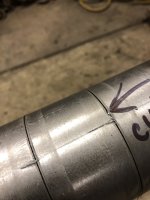
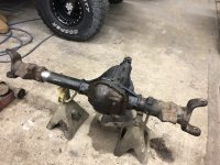
If you look close at the pics you can see the faint sign of a joint between the c and cast wedges. The 2 are married together over a short piece of 3”x1/2” tubing. I have cut them off in the past.Here's a question for jamesroney, stupidboy and anyone else who may know.
I'm as adamant as jamesroney about getting caster right, but all of my cut n' turn experience is limited to low pinion Bronco Dana 44's. I have probably seen a high pinion 44 but never looked closely. I just studied the pix in post #51. Unless I'm missing something, it seems to me that on a HP 44 with the cast ends, caster is what it is. The relationship between the radius arms (via cast-in C bushings) and inner C's is fixed. Only thing you can change is the pinion angle. Is that correct?
I don't have a dog in the fight but I like to learn, on those increasingly rare days when I'm still capable of that.
It is 3” but just at those 2 areas about 2-3/4” long the rest of the tubing is 5/16” wall.I don't think you are going to find a 1/2 inch wall tube anywhere on a cast wedge housing. Buy you will know better than me. Take a look at the end of the tube in your inner C, and tell me if it looks like 1/2 inch thick hollow-bar. I'm 99% sure that the inner tubes are 5/16 wall. I suppose it's possible that the inner C is 2-3/4 x 1/2 wall.
But you just extracted yours. So please tell me.
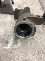
So it would appear to me that, whether Mr. Ford or anyone else intended it, the inner C on that one piece (call it cast or what ever) unit that contains wedges and said C can be sawed apart, thus ending the relationship. Set wedges (pinion) to what you want. Set inner C's to what you want. All one big happy (welded) family.
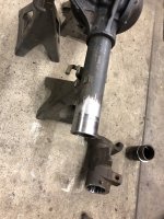
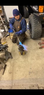
I pulled it apart like this and may do the other side but I’m going to put under the bronco first to see weather or not I need to.
Attachments
-
 ED719DD7-6A40-4FCF-9212-E527665AA313.jpeg142.1 KB · Views: 83
 -
 C7A0056C-1CC4-4494-817C-A7AA17B4D3CC.jpeg270 KB · Views: 84
 -
 3F66816E-E1A9-4172-A139-D057C64EEC8F.jpeg234.5 KB · Views: 89
 -
 3BCEB593-AF78-41A4-B8A2-FFAD0CC04346.jpeg107.1 KB · Views: 83
 -
 3B3B7B36-B6CA-4538-A709-D88B6689AED9.jpeg251 KB · Views: 88
I have torch envy...I pulled it apart like this and may do the other side but I’m going to put under the bronco first to see weather or not I need to.
Jamesroney that 3” 1/2” wall tubing I talked about is actually machined to about 7/16” and is part of the cast wedges the c is pressed onto that then welded.
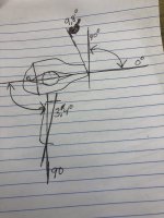
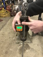
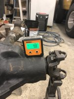
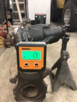
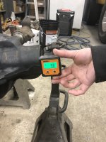
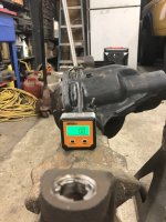
Got some numbers for ya Jamesroney and hope they are what you’re looking for.
Attachments
-
 15C06BE4-773F-4836-8E89-F17D632B0026.jpeg138.2 KB · Views: 98
 -
 72B0482F-0EEB-4341-86FC-1931E91FB177.jpeg180.6 KB · Views: 96
 -
 5DBD9F55-42BB-4580-A0A6-45C6B49BCE25.jpeg160.5 KB · Views: 86
 -
 DA0EA588-CAE5-418B-8496-8646821043EF.jpeg117.9 KB · Views: 82
 -
 E7F1C012-BEEE-4496-88AB-FC9D4017001A.jpeg168.9 KB · Views: 83
 -
 8EDABEF5-5AB1-44CC-BE1B-A5340F00CC6D.jpeg164.4 KB · Views: 95
I have confirmed that already or I would not have given these numbers to you.
When I go back to the garage I will get pics of my confirmations of this. I know you don’t want to be wrong about it and I get it!Almost what I need. There's a couple off details that will help. Can you take a tape measure and ensure that the distance from the garage floor to the pointy tip of the wedge is equal? I just want to confirm the wedge is machined "square."
Also, there is a flat spot ground on to the bottom of the inner C at the lower ball joint nut location. Can you confirm the 3.8 degree number on that flat?
thanks!
- Joined
- Aug 22, 2005
- Messages
- 14,494
Im looking at the pictures, and I have a couple questions. The 9.8 on the pinion angle. Can I assume that is the angle that the pinion needs to be set at to be in line with the driveshaft? The 3.4 is that going to be your finish castor angle?
No, on both counts. These #’s are for comparison purposes.Im looking at the pictures, and I have a couple questions. The 9.8 on the pinion angle. Can I assume that is the angle that the pinion needs to be set at to be in line with the driveshaft? The 3.4 is that going to be your finish castor angle?
- Joined
- Nov 28, 2001
- Messages
- 10,379
In looking at the original pics, I think that slight angle difference might be chalked up to the ratchet handle not being centered in the bottom hole. It looks like it's pushed to one side in the bottom hole? Could that account for it? I'm in for a teachable moment too if the machined surfaces you mention aren't good for checking angles..Turns out that I'm wrong about a lot of stuff. So you probably won't fix that.
But I can't reconcile why your king pin caster number doesn't correspond to your forged knuckle top machined surface number. The 3.4 number should be the same as the 1.7 number. I'm not saying that Dana Spicer is "perfect" but they generally do know how to machine a hole.
If you can't tell me which number is correct, then I'm going to ask you to kick the pinion up until the king pin is 0 caster and ask you to square up the two machined surfaces on the knuckle to resolve the difference. I am having a hard time thinking of a way that Dana could machine the lower ball joint taper, machine the upper ball joint, thread it, and manage to miss it all by 3.4-1.7 degrees. I've been using the lower machined surface as my datum for a long time. I'm gonna feel like an idiot if there is a bias in the knuckle. Pics in a minute.
Todd Z.
Assuming (that’s dangerous) ratchet handle is pushed to one side top and bottom.
Ratchet handle may be tapered?
Small diameter of both tapered holes probably not the same?
One taper is machined in casting, other is machined in threaded fitting that is then screwed into threaded casting.
Would like to have someone 3D-print a couple of tapered plugs with a straight thru hole, that would accept a standard diameter drill rod, for checking angles.
Similar threads
- Replies
- 7
- Views
- 878
City: Hockessin
Price: $1250
- Replies
- 1
- Views
- 657
City: Smithfield
Price: $400
- Replies
- 0
- Views
- 357
- Replies
- 31
- Views
- 3K
- Locked
- Replies
- 0
- Views
- 456


