









• Welcome to ClassicBroncos! - You are currently viewing the forums as a GUEST. To take advantage of all the site features, please take a moment to register. It's fast, simple and absolutely free. So please join our community today!
    If you have problems registering or can't log into your account, please contact Admin.

Disconnect Wiring Help

NJBronk

Contributor
Sr. Member
Joined
Oct 11, 2022
Messages
369
I hate electrical…

I’m planning to install this Painless battery disconnect: https://www.summitracing.com/parts/prf-30206

I want it mainly to de-energize the main harness while it’s parked to avoid any surprise shorts or anything when I’m not in the Bronco. I’m not concerned about breaking the path to the starter directly and not as first line theft deterrent.

I have a high torque starter that is wired by putting the battery and starter cable on the same side of the starter solenoid and then the signal wire on the switched side.

The disconnect instructions place it between the battery and starter solenoid, but I don’t want to put the entire starter load through the disconnect if I can help it.

So I’m thinking of the following:

Starter solenoid has battery and starter cables on the one side, then run another cable from that same side through a mega fuse to the disconnect. Then put the harness on the other side of the disconnect. That way the harness is disconnected and the Bronco wouldn’t start because the ignition switch doesn’t have power, but the starter load is straight through.

My first question is: does this work?

Second: where should I put the alternator wire? Do I leave it on the powered side of the starter solenoid with the battery/starter cable? Or should it go on the switched side of the disconnect with the harness?

I want to make sure I wouldn’t have an issue with the alternator if the power is cut via the disconnect while the engine is running (either accidentally or in an emergency), not sure if that’s possible.

Third, can someone confirm the thicker black wire below (with the fuse) is the alternator and the yellow wire is the harness? The black wire branches off from the bundle coming from the alternator, but I didn’t want to just assume in case there was something I don’t understand.

Lastly, can someone confirm the gauge of the yellow wire? I want to crimp a new ring terminal on there.
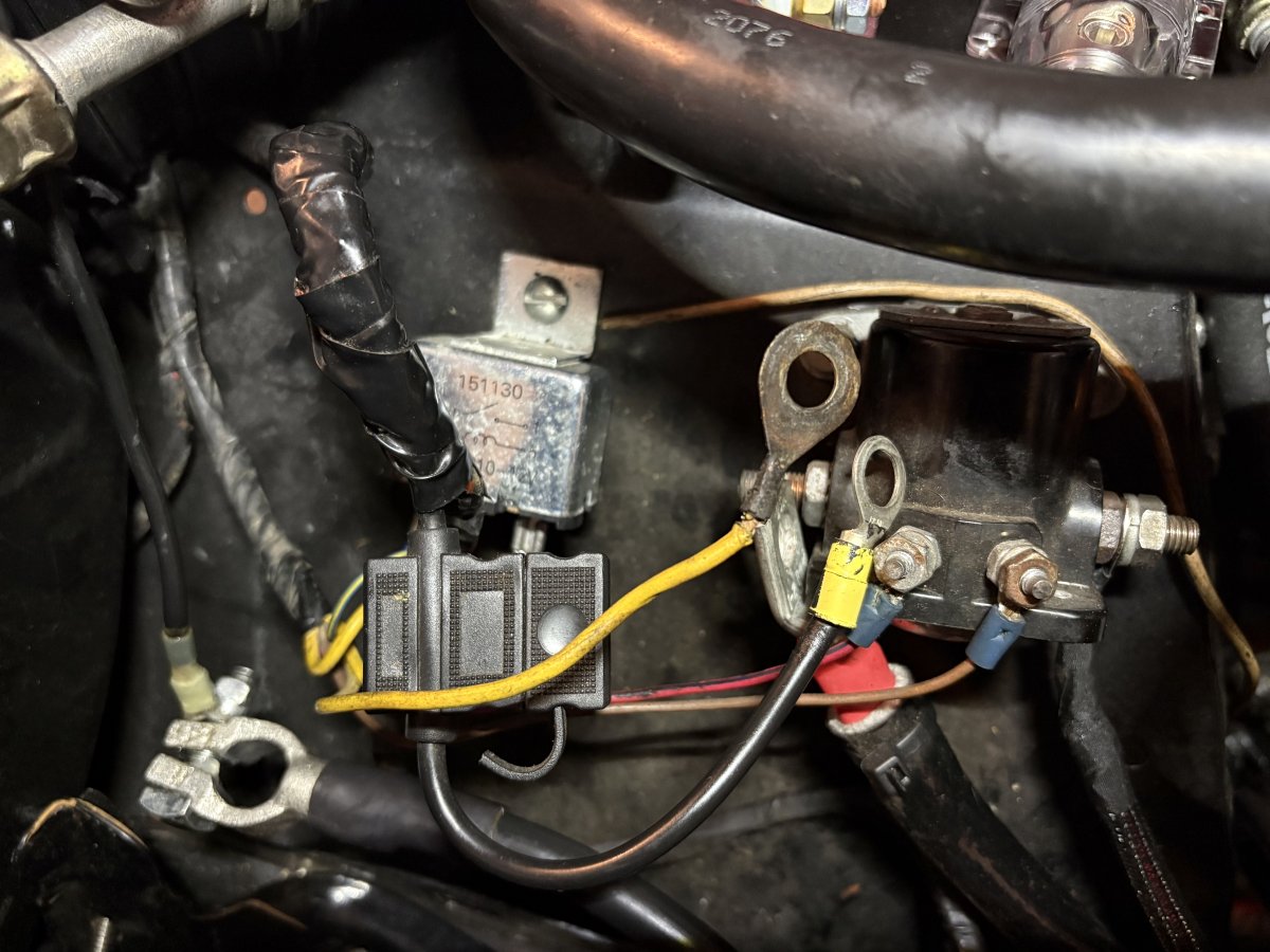
IMG_5767.jpeg
 
Last edited:

DirtDonk

Contributor
Bronco Guru
Joined
Nov 3, 2003
Messages
51,650
What year is your bronco?
Is that still a factory yellow wire? If so, it’s probably 14 gauge.
I see a lot of nonstock stuff around there, including what looks to be an air-conditioning hose and a nonstock relay of some type.
What else has been done to the vehicle, including Wiring?

Your preferred scenario is basically correct.
Or at least part of it.
Yes, you definitely don’t want that disconnect in the main battery cable circuit.
You want to shut off power to the rest of the vehicle via the wire from the starter relay to the cabin/fuse panel.
Is that the black wire with the fuse? Probably someone (perhaps you?) changed out the fusible link to a fuse. What is its rating?
Is the other side connected to the original black wire? If so, then it’s 10 gauge. Which the new black wire looks to be as well.

What Alternator do you have?
And what type of wire do you have going from the alternator to the starter relay now? Is it original?
Maybe it’s my eyes, but I can’t see all of the wires that there should be there.
Only you can verify where each wire goes once they’ve been changed and things have been altered.
 
OP
OP
NJBronk

NJBronk

Contributor
Sr. Member
Joined
Oct 11, 2022
Messages
369
That’s part of the problem, the PO did a number of things…. It’s a ‘74, but he upgraded to a later Duraspark (spliced together, not using factory connections). There is an aftermarket A/C but no other accessories.

The black and yellow wires were attached to the same solenoid stud as the battery cable, so I assumed the black must be the alternator and yellow the harness? I believe the yellow wire is factory as most of the harness is. There was nothing else on the solenoid.

The fuse is 30 amps.

I have no idea how to tell what alternator I have. Here are a couple pictures, if that helps (no label that I can find):

IMG_5769.jpeg


IMG_5770.jpeg
 

Oldtimer

Contributor
Jr. Member with Sr. moments
Joined
Feb 4, 2005
Messages
1,801
Loc.
Sunnyvale, CA
Can you post a picture that shows the alternator, starter relay, battery, and fender back toward the firewall.
Need an overall picture of harness and connections.
 

DirtDonk

Contributor
Bronco Guru
Joined
Nov 3, 2003
Messages
51,650
That’s why I was asking about the black wire.
The black wire at the relay is normally the power feed to the entire vehicle.
The yellow wire is the horn relay power.
There’s another yellow wire spliced in, deeper into the harness, for the voltage regulator.
The wire off of the alternator usually is black, or a black with a red stripe, and goes to the firewall. Well, goes to the firewall via circuitous route in the harness.
So at some point, there are two black wires running along relatively parallel to each other into the firewall.
One is from the Alternator’s BAT Output terminal, goes into the passenger compartment, feeds the fuse box and ammeter and other accessories, then comes back out to become the black with yellow wire at the starter relay. It is one long wire with a connector at the back of the ammeter.
Basically a loop. We call it the ammeter loop for those that know how the Bronco is laid out.
When the vehicle is not running, the battery feeds everything. When the engine is running and the alternator working, it powers, everything and recharge the battery at the same time. That’s why a typically good Alternator puts out about 14.5 V, so that the more powerful Output will literally “push“ juice back into the Battery. For lack of a better description…
So you may see two black 10 gauge wires running around. Don’t get confused by them.
But that’s why I wanted to know if the Alternator wire had been somehow spliced into the other wire. Other vehicles without an ammeter, or with a different type, run the Alternator Output directly up to the same stud on the starter relay.
Broncos run a long loop.
 

DirtDonk

Contributor
Bronco Guru
Joined
Nov 3, 2003
Messages
51,650
Oh, and it looks like a standard Ford Alternator.
Newer one by the looks of it.
In the old days they were had anywhere between 35 A and 45 A of output. In later years, they were usually 50 or 55. When bought as replacements in more recent years, they can be up to 60 or 65 A.
Very likely then, yours is somewhere between 50 and 65.
 

Oldtimer

Contributor
Jr. Member with Sr. moments
Joined
Feb 4, 2005
Messages
1,801
Loc.
Sunnyvale, CA
In theory this wire should be BK/YL.

1779676894844.png


It is 12v charge from alternator, disappears into harness, and runs to back of dashboard.
There are taps off of it to: ignition switch, headlight switch, and fuse block.
It is terminated at a bullet connector that plugs into a black wire.
The black wire passes thru ammeter loop, and dissapears into harness, reappearing with an eye terminal that connects to the B+ stud on starter relay (along with battery + wire).

1779677393943.png


The YL wire with eye terminal is also connected to B+ stud on starter relay.The YL wire goes to the regulator, and tells the alternator to charge the battery, when needed horn relay.
EDITED, MAY 25.

1779677902979.png


1779677985698.png


1779678808277.png
 
Last edited:

Oldtimer

Contributor
Jr. Member with Sr. moments
Joined
Feb 4, 2005
Messages
1,801
Loc.
Sunnyvale, CA
The yellow wire is the horn relay power.
Maybe. . . . Horn relay was added in 75-77 harness.
Up until 74ish there was no relay. 12v ran thru the two contacts in turn signal switch.
When relay was added, there was only one contact in turn signal switch.
 

DirtDonk

Contributor
Bronco Guru
Joined
Nov 3, 2003
Messages
51,650
Not quite. The relay was added at some point in the '74 model year run. Early '74's did not have it, and later ones did.
Hence all the crap everyone goes through with '74 steering columns. Some of which extends to '73 and '75 columns as well!
But relays can absolutely be found on some '74's, and the regulator Yellow wire is (usually) not connected visibly to the starter relay. It's a splice buried in the harness tape.
Your diagram shows it as a splice, and not as a connection to the relay.

That's been my experience at least. Check yours out and let us know if there is a Yellow wire on the relay. The '68 should, in theory, be the same as my '71. My '68 has been re-wired with Centech, so not good as a reference.

Paul
 

DirtDonk

Contributor
Bronco Guru
Joined
Nov 3, 2003
Messages
51,650
But this conundrum is a good reason for those extra photos you asked for earlier.
Not sure what the relay/thingy is in his earlier pic, but if we see a factory style horn relay on the inner fender apron, we'll know his has one.
Or NJ could just tell us! Hah!
But pics are still best.

Keep the pics coming NJ. Yours are actually great shots. Be we love pics around here.

Paul
 

DirtDonk

Contributor
Bronco Guru
Joined
Nov 3, 2003
Messages
51,650
Sorry I haven't had time to get the '68 put back together. Was hoping to bring it to the restaurant for the gathering in a couple of weeks.:(
Speaking of electrical though, I'm still going to bring the new Classic harness for anyone that wants to check it out though. We can even spread it out on your hood in the parking lot!
You will be there, I hope?

Sorry for the slight hijack NJ. Just catching up with another local.

Paul
 
OP
OP
NJBronk

NJBronk

Contributor
Sr. Member
Joined
Oct 11, 2022
Messages
369
Thanks, all. My eyes are glazing over trying to read and understand everything. Maybe after my coffee…

Truck was built in Nov. of ‘73, if that makes a difference.

Battery is out of the truck, but I hooked everything back up to the starter solenoid as it was. Red cable to the starter has a heat shield on it, and signal cable to starter has a loom. Red cable goes to battery.

Here are some pictures:

IMG_5771.jpeg


IMG_5774.jpeg


IMG_5772.jpeg


Red and black wires below the harness here are for the disconnect, they will get loomed once I figure out how to hook it up…

IMG_5773.jpeg


IMG_5780.jpeg
 
OP
OP
NJBronk

NJBronk

Contributor
Sr. Member
Joined
Oct 11, 2022
Messages
369
I’m also thinking of moving the heavy duty battery and starter cables to a stud junction since they’re so thick and run one cable to the starter solenoid and another to the shutoff/harness. Still just don’t know what to do with the black and yellow wires. Sounds like black is the harness and yellow is from the regulator? Could I put them both on the switched side of the shutoff?
 
Last edited:

Oldtimer

Contributor
Jr. Member with Sr. moments
Joined
Feb 4, 2005
Messages
1,801
Loc.
Sunnyvale, CA
I would agree with Dirtdonk, from what I see in photos.
Yellow appears to be power to horn relay.
Looks like it goes from relay into harness, doubls back and goes to B+ stud on satrter relay.
You may be able to tell by touch, or peel harness wrap back.

1779736080964.png


You could also reconnect every thing except the yellow, and see if horn works.

The schematic for 74ish to 77 shows the yellow wire from horn relay, with a note that it connects to starter relay.

1779736482189.png
 
OP
OP
NJBronk

NJBronk

Contributor
Sr. Member
Joined
Oct 11, 2022
Messages
369
Thanks. I’ll try the horn with the yellow disconnected when I put the battery back in.

So does my plan of hooking both the black and yellow wires to the switched side of the shutoff make sense / not cause any issues?
 
OP
OP
NJBronk

NJBronk

Contributor
Sr. Member
Joined
Oct 11, 2022
Messages
369
I’ve been going down a rabbit hole and now think I might wire a charging cable from the alternator directly to the battery (with a fuse) to remove the amperage from the harness, and then I believe I could wire the black harness and yellow horn relay on the switched side of the disconnect.

Otherwise, accidentally hitting the disconnect while the engine is running would disconnect the alternator from the battery and possibly cause surging/other electrical issues.

I think I can leave the stock charging cable in place and just add the heavy gauge fused cable and the charging will take the path of least resistance and not put the load on the harness?

Sound reasonable?
 
Last edited:
OP
OP
NJBronk

NJBronk

Contributor
Sr. Member
Joined
Oct 11, 2022
Messages
369
Made a diagram with a little help from ChatGPT... This is assuming the current alternator harness stays connected as-is and I just add another charging cable directly from the alternator to the distribution block. Any concerns or improvements/corrections to make?

Disconnect Wiring.png
 

DirtDonk

Contributor
Bronco Guru
Joined
Nov 3, 2003
Messages
51,650
I’ve been going down a rabbit hole and now think I might wire a charging cable from the alternator directly to the battery (with a fuse) to remove the amperage from the harness, and then I believe I could wire the black harness and yellow horn relay on the switched side of the disconnect.

Otherwise, accidentally hitting the disconnect while the engine is running would disconnect the alternator from the battery and possibly cause surging/other electrical issues.

I think I can leave the stock charging cable in place and just add the heavy gauge fused cable and the charging will take the path of least resistance and not put the load on the harness?

Sound reasonable?
Yes. Should work well that way.
Leaving the stock Black wire in place however, does have its downsides.
And keeping the yellow wire on the Battery side would allow the horn to work whether the disconnect is on or off. And horns rarely drain the battery.
But it’s not impossible, so you could do either way with the yellow.
 

DirtDonk

Contributor
Bronco Guru
Joined
Nov 3, 2003
Messages
51,650
Made a diagram with a little help from ChatGPT... This is assuming the current alternator harness stays connected as-is and I just add another charging cable directly from the alternator to the distribution block. Any concerns or improvements/corrections to make?

View attachment 962455
Just some “just in case” concerns.
As I mentioned in the previous post, having two charge wires does have its downsides.
On the good side, your ammeter will still show a drain if you leave something on with the engine off. That’s a nice little safety indicator.
On the downside, that’s just extra wire connectors on the output stud of the alternator.
Not horrible, but gets a little crowded down there.
The real downside I see, is that if your fuse ever blows on the new main wire, your old wire still works. Depending upon what blew the fuse, that could be dangerous.
It’s not a huge concern necessarily, with the stock alternator, as long as you leave that other fuse in the other end of the black wire, but if you ever upgrade to a higher output version, then absolutely leave the old wire off and out of the equation.
 

DirtDonk

Contributor
Bronco Guru
Joined
Nov 3, 2003
Messages
51,650
Although I do have an issue with the diagram.
Is that a Buss bar, or individual circuits? Either way, the way it’s shown I’m not sure how the circuit disconnect would actually disconnect anything.
If it’s just for a clear layout of individual pieces, no problem. Just make sure you know where all the power goes! :)
 
Top