• Welcome to ClassicBroncos! - You are currently viewing the forums as a GUEST. To take advantage of all the site features, please take a moment to register. It's fast, simple and absolutely free. So please join our community today!
    If you have problems registering or can't log into your account, please contact Admin.

Sniper pink wire

badandy73

Contributor
Broncoholic
Joined
Jul 18, 2007
Messages
159
On the downhill side of a blueprint 306 swap along with an explorer serp. conversion and sniper install.

For you guys running the sniper, where did you tap into to get your key on and crank power signal? Running a painless harness and talked with them; first they recommended the #920 wire, which seems to be frowned upon in the holley instructions as it's part of the coil wiring and then the tech said to just run it to the back of the ignition switch. That doesn't seem like the cleanest solution, being as the fuse block has all those nice accessory circuits that I thought would be great to utilize for something like this.

Any input from you guys that have done this?
 
Last edited:

Calibronc66

Full Member
Joined
Dec 15, 2016
Messages
253
What I had to do because it would fire up then die because I wasn’t getting a clean signal to the pink wire. I used the positive coil wire to switch a relay then came out of the relay to turn on the sniper, cdi, and distributor all the pink wires ran great.


Sent from my iPhone using Tapatalk
 

Broncobowsher

Total hack
Joined
Jun 4, 2002
Messages
35,281
Does your painless harness have a ballast resistor?

The other glitch is the switched ignition at the key is often flakey while in start. In the original wiring that isn't an issue as the ignition gets power from the bypass wire on the starter solenoid. So if you really want it right, you need both the switched ignition and the bypass wire tied together for a switched ignition source. And if there isn't a ballast resistor, you are good to use the painless ignition wire. The frowned upon wire tap is when you pull power after the ballast resistor, that is dirty power as the coil fires and when the coil is charging the voltage is low, and what the ECM pulls for power reduces the spark output. So after a ballast resistor it is a lose, lose, lose situation. Before (or without) a ballast resistor, same as the back of the ignition switch.
 
OP
OP
badandy73

badandy73

Contributor
Broncoholic
Joined
Jul 18, 2007
Messages
159
Thanks Calibronc.. have heard of similar setups, was just hoping to avoid wiring up a relay if possible.

What I had to do because it would fire up then die because I wasn’t getting a clean signal to the pink wire. I used the positive coil wire to switch a relay then came out of the relay to turn on the sniper, cdi, and distributor all the pink wires ran great.


Sent from my iPhone using Tapatalk
 
OP
OP
badandy73

badandy73

Contributor
Broncoholic
Joined
Jul 18, 2007
Messages
159
Running a flame-thrower coil without a ballast resistor, so it sounds like I should just be able to run it off the + side of the coil?

Does your painless harness have a ballast resistor?

The other glitch is the switched ignition at the key is often flakey while in start. In the original wiring that isn't an issue as the ignition gets power from the bypass wire on the starter solenoid. So if you really want it right, you need both the switched ignition and the bypass wire tied together for a switched ignition source. And if there isn't a ballast resistor, you are good to use the painless ignition wire. The frowned upon wire tap is when you pull power after the ballast resistor, that is dirty power as the coil fires and when the coil is charging the voltage is low, and what the ECM pulls for power reduces the spark output. So after a ballast resistor it is a lose, lose, lose situation. Before (or without) a ballast resistor, same as the back of the ignition switch.
 

LSUpete

Contributor
Bronco Guru
Joined
Jul 11, 2001
Messages
2,063
If you have the Painless harness, Why don’t you just use any of the switched power accessory wires (#5 thru #8) on the fuse panel?
 

Broncobowsher

Total hack
Joined
Jun 4, 2002
Messages
35,281
You don't want the EFI running off accessory power, you want it running on ignition power.
 

LSUpete

Contributor
Bronco Guru
Joined
Jul 11, 2001
Messages
2,063
You don't want the EFI running off accessory power, you want it running on ignition power.

Thanks. I have my installation complete and will be performing the initial start-up this weekend. I WAS going to use one of the accessory wires....

I have an HEI style distributor that eliminates the ballast resistor.

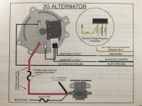
I also have a 3G alternator, and have eliminated the voltage regulator, my sense is that the Painless Harness GREEN/red stripe wire is the correct place to connect the Sniper PINK wire. Is that correct?

By the way, Painless says to tap into the #933 BLACK/green stripe wire feeding the ignition switch.
 

Attachments

  • 571428B1-95DE-4C16-8076-E7D9AE85DEB8.jpg
    571428B1-95DE-4C16-8076-E7D9AE85DEB8.jpg
    84 KB · Views: 46
Last edited:

LSUpete

Contributor
Bronco Guru
Joined
Jul 11, 2001
Messages
2,063
Okay, I did a little digging into this with the Painless Wiring technical support.

The Painless Harness GREEN/red stripe wire is NOT the correct place to connect the Sniper PINK wire. That GREEN/red stripe wire is only hot while cranking....not in the "run" position.

The Painless Tech Rep suggested the #920 RED/green stripe wire but again, Holley doesn't consider that coil wire to be a clean connection.

The Painless #954 WHITE/black stripe "electric choke" wire was also recommended because it DOES have power while cranking AND in the run position.....and that wire is abandoned when you install the Holley Sniper.
 

lonesomecur

Contributor
Full Member
Joined
Dec 7, 2007
Messages
333
I’ve had my sniper installed for a week now. I used one of the Switched ACC Wires on the painless harness. Working great so far.

Why would you not want to use that. It’s switched, hot during cranking and run position??? Someone please explain if you know.
 

Broncobowsher

Total hack
Joined
Jun 4, 2002
Messages
35,281
Fuel injection is live in accessory position. Sort of defeats the idea of accessory position.
 

DirtDonk

Contributor
Bronco Guru
Joined
Nov 3, 2003
Messages
48,486
That GREEN/red stripe wire is only hot while cranking....not in the "run" position.

I think the phone tech was confused. Unless Painless has made a major change, the Green w/red is hot in both. It's only the Red w/blue stripe wire that is hot in START only.
Same as Ford.

The Painless Tech Rep suggested the #920 RED/green stripe wire but again, Holley doesn't consider that coil wire to be a clean connection.

Not sure why that would be from Holley's standpoint. Other than the flakiness with older switches that was mentioned. With a new switch that should not be an issue (assuming it's good out of the box that is).
Maybe it's a "noise" issue with the positive side of the coil. Now that would probably make sense. A relay does eliminate that noise most likely, but as you said, you wanted to avoid the additional relay.

The Painless #954 WHITE/black stripe "electric choke" wire was also recommended because it DOES have power while cranking AND in the run position.....and that wire is abandoned when you install the Holley Sniper.

That's good to know. From the factory that is the stator wire from the STA terminal of the alternator. But with Painless it's powered through the fuse panel instead. I did not know it was on the same circuit as the Red w/green and Green w/red from the switch. Good info.
That would seem like a great source then. Even though it's functionally the same as the Red w/green coil wire, it's coming from farther away and maybe does not have the same type of issues as the coil wire does in Holley's eyes.
Maybe member Eric here (designer of the Painless harness) can shed any additional light on the subject.

Paul
 

DirtDonk

Contributor
Bronco Guru
Joined
Nov 3, 2003
Messages
48,486
I also have a 3G alternator, and have eliminated the voltage regulator, my sense is that the Painless Harness GREEN/red stripe wire is the correct place to connect the Sniper PINK wire.

Is this a standard 3G? Are you still using the Green w/red wire for the internal regulator like in the diagram?
Generally speaking though, I would think it would be a workable wire, just like the White w/black and the Red w/green.

Paul
 

LSUpete

Contributor
Bronco Guru
Joined
Jul 11, 2001
Messages
2,063
Is this a standard 3G? Are you still using the Green w/red wire for the internal regulator like in the diagram?
Generally speaking though, I would think it would be a workable wire, just like the White w/black and the Red w/green.

Paul

Yes, I followed the diagram and the Bronco has run perfectly.

My biggest concern, and likely the biggest concern from everyone, with the Sniper is radio frequency interference. I've heard that it can be maddening to get worked out, so I want to make certain that I don't start off with a 12v switched connection that lends to that RFI issue.

Is connecting (through the dash) to the #933 BLACK/green stripe wire feeding the ignition switch a good idea?
 

DirtDonk

Contributor
Bronco Guru
Joined
Nov 3, 2003
Messages
48,486
Sorry Pete. Meant to answer that in the first response but wanted to consult the book and got sidetracked instead.
I've talked to Eric about this before, but in the original harness the Black w/green wire was an ACC wire and was hot in both ON and ACC, but not in START. The Painless is a little different so I wanted to see how it is in my old book, then check the new one to see if they've changed anything.
Speaking of that... Is this a newer purchase, or have you had the harness for awhile now?

Paul
 

DirtDonk

Contributor
Bronco Guru
Joined
Nov 3, 2003
Messages
48,486
Ok, with Painless the Black w/green #933 wire IS the switched power to the main fuse panel. So apparently ALL of the switched fuses are hot in both ON and START from the switch. I remember Eric mentioning this once, but I never followed up on just how that was accomplished.
The Painless Black w/green wire is on the terminal of the switch that is usually populated by the Green w/red wire and the Red w/green wire. So instead of just powering the ignition and the voltage regulator exclusively, several more accessory circuits are also powered up.
I wonder if all the switched circuits are handled this way, or if there is a split. Eric?;D

The Orange #932 wire from the center ACC post of the ignition switch powers an auxiliary fuse group, instead of all the other accessories.

I also wonder if the switched fuses are handled by a relay, or if all the power for the entire switched bank is pulled through the ignition switch. That does not seem to bode well for the life of the switch, but maybe the newer switches are better, or with better electrical flow there is not as much load on the switch.
Don't see how, but I suppose it's possible.

Anyway, as far as your Pink wire's needs are concerned then, it seems you can do "all of the above" and connect it just about anywhere in the system.
You could use the Green w/black, but that would not only be un-fused but would be between the switch and a whole lotta' loads at the other end (the entire half of the fuse panel) too, so might be noisy with RFI.
You could use the Green w/red wire, but it's kind of the same thing.

The best route I think would be to use fused circuit #'s 5, 6, 7 or 8 (as you mentioned before) in the "switched" section of the main fuse panel. These are "ON"only, which in this case means hot in ON/START, but not ACC. Which is what you want think.
These are not sharing anything with anything, other than the main buss-bar in the fuse panel. Seems like it's isolated enough for the needs of the computer then.

I'm going to ask Eric a couple of these questions, and maybe he can join in this discussion too and correct me if I'm wrong on the fuse numbers and their functionality.

But that's what I know for now...

Paul
 

DirtDonk

Contributor
Bronco Guru
Joined
Nov 3, 2003
Messages
48,486
Gotcha. That can sometimes make a difference, but in this case it doesn't look like they made any changes in the meantime. The Black w/green wire from the ignition switch is still the main source of switched power in ON/START for the fuse panel.
The Orange wire is ACC and ON, but not in START.

Paul
 

eric0o1

Sr. Member
Joined
Apr 17, 2008
Messages
592
Paul is correct, all of the switched circuits on the harness coming from the main fuse block will be HOT in the ON/RUN position as well as the Start position. These include heater switch, wiper switch, gauge cluster, turn signal/reverse, coil, electric choke, and Accessory wires #5-#8. The green/red at the regulator n the ON/RUN position as well as the Start position, I'm not certain why our tech would tell anyone otherwise, but I am sending an email to the 3 of them to make sure misinformation doesn't get spread.

The only wires that will lose power in the Start position are those wires coming from the smaller auxiliary fuse block as these receive power from the accessory post on the ignition switch. These are switched power to the radio, panel back lighting, and accessory wire #9.

PDF page 17, manual page 10 shows these wires
https://www.painlessperformance.com/Manuals/10113.pdf

All of the switched power does go though the switch without the use of relays. Any high amperage demands that would overload the switch should be on their own separate relays
 

LSUpete

Contributor
Bronco Guru
Joined
Jul 11, 2001
Messages
2,063
Paul is correct, all of the switched circuits on the harness coming from the main fuse block will be HOT in the ON/RUN position as well as the Start position. These include heater switch, wiper switch, gauge cluster, turn signal/reverse, coil, electric choke, and Accessory wires #5-#8. The green/red at the regulator n the ON/RUN position as well as the Start position, I'm not certain why our tech would tell anyone otherwise, but I am sending an email to the 3 of them to make sure misinformation doesn't get spread.

The only wires that will lose power in the Start position are those wires coming from the smaller auxiliary fuse block as these receive power from the accessory post on the ignition switch. These are switched power to the radio, panel back lighting, and accessory wire #9.

PDF page 17, manual page 10 shows these wires
https://www.painlessperformance.com/Manuals/10113.pdf

All of the switched power does go though the switch without the use of relays. Any high amperage demands that would overload the switch should be on their own separate relays

Thank you Eric.
 
Top