• Welcome to ClassicBroncos! - You are currently viewing the forums as a GUEST. To take advantage of all the site features, please take a moment to register. It's fast, simple and absolutely free. So please join our community today!
    If you have problems registering or can't log into your account, please contact Admin.

Voltage regulator problem?

NO BS

New Member
Joined
May 11, 2011
Messages
22
Loc.
durham,nc
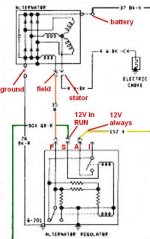
I PUT ON A NEW VOLTAGE REGULATOR CONNECTOR AND LOST A VOLT ACROSS MY CHARGING SYSTEM (WAS 14.5 NOW IS 13.65)FROM THE VRC IASF I=12v WITH THE KEY ON
A= 2 WIRES 12.5 ALWAYS (1 CONNECTED ONE NOT)
S= 2 WIRES 11.6 KEY ON (1 OF THESE IS CONNECTED TO THE GREEN WITH RED STRIPE WIRE FROM THE TRUCK HARNESS.)1 CONNECTED ONE NOT
F= 12V KEY ON
ALSO FROM THE ALT POST (STA) THE WIRE COMES OUT OF THE TRUCKS HARNESS AT THE VRC BUT ISN'T CONNECTED TO ANYTHING
ANY HELP WOULD BE APPRECIATED
BS
 

DirtDonk

Contributor
Bronco Guru
Joined
Nov 3, 2003
Messages
48,356
I think your wire orientation is wrong. Correct for a vehicle with a dash indicator lamp, but not for a Ford with an ammeter.

Wiring should be as follows for your Bronco:

F terminal: Orange wire to FIELD terminal on back of alternator.
S terminal: Green w/red wire on with the key.
A terminal: Yellow wire with full battery voltage all the time.
I terminal: Unused on a Bronco.

Make sure your connections are good. A large enough voltage drop on the wires can cause issues. You should read full battery voltage at both the Green w/red wire and the Yellow wire. The Yellow wire is the more critical, but check them both anyway.
And you may have 2 Yellow wires, as one goes to the radio noise suppressor mounted to the fender. Assuming your '66 would have been so equipped that is.

Did you change the regulator itself? Any other changes that could have caused a change?
Nevermind, I see you did change the regulator. Check those things first, but if that doesn't yield any fixes, maybe try the old regulator again?

Paul
 

DirtDonk

Contributor
Bronco Guru
Joined
Nov 3, 2003
Messages
48,356
Ok, re-read it again (a little slower this time) and see that it's generally hooked up as it's supposed to be.
Just not sure why you have anything to the I terminal, unless that voltage reading is strictly from the regulator itself, and there is no wire there. That correct?
That's a pretty substantial voltage drop on the "S" wire. Until last week, I would have thought this would be an issue. Viperwolf assures us that it's not. But it still means you have a weak connection to the ignition switch.

Paul
 

DirtDonk

Contributor
Bronco Guru
Joined
Nov 3, 2003
Messages
48,356
Should not have been a stator wire off the alternator on yours I don't think. I know we're always finding unusual things with the '66 models, but this would be the first time I've heard of that.
Unless yours is a really early one, and perhaps Ford was still experimenting?

Is it White w/black? Or some other color?

Paul
 

Viperwolf1

Contributor
electron whisperer
Joined
Aug 23, 2007
Messages
24,342
12V on "F" means the regulator is telling the alternator to go to max charge. The F wire should be going to the FLD connector on the alternator. I'd think you should be seeing at least 14.5V at the back of the alternator and at the battery.

12V will be seen at the "I" terminal of the regulator when it is turned on (key on).
 

Attachments

  • alt-reg.jpg
    alt-reg.jpg
    37 KB · Views: 53

DirtDonk

Contributor
Bronco Guru
Joined
Nov 3, 2003
Messages
48,356
Phil, are you familiar with what definitions Ford originally intended for the letters? Seems like it would be "Field", "Stator", "Armature"(maybe, though I use "always" too) and "Ignition" to me.
Any validity to those? Never seen it listed myself.

Paul
 

Viperwolf1

Contributor
electron whisperer
Joined
Aug 23, 2007
Messages
24,342
Phil, are you familiar with what definitions Ford originally intended for the letters? Seems like it would be "Field", "Stator", "Armature"(maybe, though I use "always" too) and "Ignition" to me.
Any validity to those? Never seen it listed myself.

Paul

I used to know them. F is field, S is stator. Can't remember A. I is indicator (or idiot light). I think the GM version was something like F234. It worked exactly the same.
 

DirtDonk

Contributor
Bronco Guru
Joined
Nov 3, 2003
Messages
48,356
Yeah, was just looking at one of my '60's GM shop manuals, and in the regulator testing and adjusting section, they showed "F,2,3,4" as the regulator terminals. Where F was field, 2 was "Relay" (for field relay), #3 was the always-on battery connection and #4 was the Ignition/Indicator circuit.

I love the old factory books. They assumed you knew how to turn a wrench, and actually ran through wheel alignment, steering box, transmission and A/C compressor rebuilding (with full descriptions and pictures even) and gave detailed specifications for just about anything you might ever work on.
Of course, cars were simpler then, but still...

Thanks

Paul
 

DirtDonk

Contributor
Bronco Guru
Joined
Nov 3, 2003
Messages
48,356
Sorry for the sidetrack session NO BS.
We was just chattin' until you got back with more updates.

Paul
 
OP
OP
N

NO BS

New Member
Joined
May 11, 2011
Messages
22
Loc.
durham,nc
thanks for the help fellas!the 12v with the key on at I.is on a green wire from the vrc but its not hooked up to anything.the other question about the color of the STA wire off the ALT. is small green with a stripe believe the stripe is yellow.however it comes out of the trucks harness in front of the vrc as a black and white wire but its not hooked up to anything.when i get out of work tonight ill hook up the vr as you stated above and repost.thanks again
BS
 
OP
OP
N

NO BS

New Member
Joined
May 11, 2011
Messages
22
Loc.
durham,nc
ok finally got time to work on the truck again.ok i did a continuity check on the wires between the ALT and the VRC because most off the wires are painted it seems so colors an issue.and heres what i got.
off the ALT STA post-- comes out of the trucks harness at the VR and is not connected.
FLD post off ALT--has continuity to grd of VRC as well as I,A,S,F on VRC
GRD off ALT--same as FLD above.
BATT off ALT--+batt terminal
empty post no label on alt as well
thanks for your help
BS
 

Viperwolf1

Contributor
electron whisperer
Joined
Aug 23, 2007
Messages
24,342
ok finally got time to work on the truck again.ok i did a continuity check on the wires between the ALT and the VRC because most off the wires are painted it seems so colors an issue.and heres what i got.
off the ALT STA post-- comes out of the trucks harness at the VR and is not connected.
FLD post off ALT--has continuity to grd of VRC as well as I,A,S,F on VRC
GRD off ALT--same as FLD above.
BATT off ALT--+batt terminal
empty post no label on alt as well
thanks for your help
BS

It seems the alternator harness is not from a Bronco but from something that had an indicator light instead of an ammeter. That would explain the green wire at the "I" and the unconnected STA wire. No problem using it as long as you wire it according to the diagram above.

FLD continuity to ground--more than likely this is because of the low resistance of the field windings, I think somewhere around 2 ohms. I recommend using the lowest ohm setting on your meter when checking resistance. As long as the FLD wire is going straight to the "F" terminal you're ok.
 
OP
OP
N

NO BS

New Member
Joined
May 11, 2011
Messages
22
Loc.
durham,nc
i just did continuity checks (only thing i ohmed out was the fuses)what should i have for these wires, ohms wise?as far as an indicator light instead of an ammeter.i have what looks to be stock gauge around the steering column with an alt gauge(not sure if it works) and what looks to be added are 3 gauges (at the bottom center of dash )not sure about that one either.thanks again.
BS
 

Viperwolf1

Contributor
electron whisperer
Joined
Aug 23, 2007
Messages
24,342
i just did continuity checks (only thing i ohmed out was the fuses)what should i have for these wires, ohms wise?as far as an indicator light instead of an ammeter.i have what looks to be stock gauge around the steering column with an alt gauge(not sure if it works) and what looks to be added are 3 gauges (at the bottom center of dash )not sure about that one either.thanks again.
BS

The wires should be .5 ohm or less from end to end. It gets tricky when measuring to ground on circuits that have parallel paths. I recommend disconnecting one end of the wire first.
 
Top