


OP
OP
- Joined
- Aug 1, 2012
- Messages
- 161
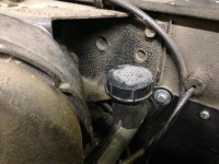
I think it depends on which master you use as to where the hole needs to be. my master has the hose coming out of the front and not the bottom and the base does not rotate like the one in tailpipes pic. it is a solid piece of plastic. I used the speedo cable hole for mine and it is working perfect. seems to be the correct ratio. Even though mine is a M5OD application, I used the ZF internal slave and matching master cylinders. I got lucky though, I didn't know that there were 2 different bores and just ordered an internal slave for the truck I took the master off of and it all worked.
Crush, you bring up an interesting point here with the two styles of master cylinders. Silas is running the same style as you are (picture in my full write-up), so now I'm scratching my head again. Actually, now that I think about it, from what I have been reading most of the hard clutch issues are coming from the guys using the style of master cylinder that I have. I would be interested in hearing what the consensuses out there is.


")