



Jdgephar
Bronco Guru
- Joined
- Sep 25, 2012
- Messages
- 1,516
I agree, it appears that the wire crimp to the terminal overheated.Looking at the picture in the first post, the heat zone appears to be centered around the crimp for the yellow wire.








I agree, it appears that the wire crimp to the terminal overheated.Looking at the picture in the first post, the heat zone appears to be centered around the crimp for the yellow wire.

This is not a good circuit design. The 12V Bosch relay is redundant, and weaker than the Volvo relay, so it's unnecessarily creating the problems you're having. But as others have noted - your problem was a poor crimp or other high resistance at the yellow wire on the Bosch relay....this is how I have it wired currently...
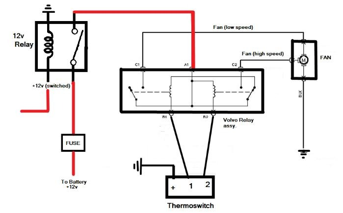
That's pin 30 on the Bosch relay....from the battery (pin 87 on the relay, 12V in with a 30A fuze inline)...
That's pin 87 on the Bosch relay....Pin 30 (to the Volvo relay).
That's not really an improvement.I'm going to bump to a bigger relay...


This is not a good circuit design. The 12V Bosch relay is redundant, and weaker than the Volvo relay, so it's unnecessarily creating the problems you're having. But as others have noted - your problem was a poor crimp or other high resistance at the yellow wire on the Bosch relay.
That's pin 30 on the Bosch relay.
That's pin 87 on the Bosch relay.
That's not really an improvement.
The toggle switch at the right side of the diagram is only there to disable the fan (by controlling the Bosch relay) when the key is ON. That can be accomplished by putting that switch (ALONE - no relay or fuse) into the wire from the temperature switch to ground. Then the red wire from the Volvo pin 30 can go through the fuse directly to the battery (but it shouldn't be physically attached to the battery - it should be on the starter relay's always-hot post with the alternator output & feed to the Bronco's wiring). Another improvement is to run the fan return wire directly to the battery (-) or to another ground point (like the main block ground) that has a larger return wire (like the black battery cable) so that it runs through wire the whole way (not really grounded).

Was your thermal switch on the radiator or intake manifold? Mines on the intake manifold, and was thinking the fan would run for a really long time, key off if I don't have anything circulating the water from the block to the radiator. The rad would cool way before the block.Power to the Volvo relay would be hot all the time. That's a non-issue because the control gets switched on and off with the IGN. My '84 Rabbit diesel ran the cooling fan whether the IGN was on or not. If the sensor said it needs to run, it ran. I wired the electric fan on the Ranchero to work the same way.
No, I'm saying you were referring to them backward. I can't see how they're wired - only how your diagram showed them, and what you said about that diagram....are you saying I had 30 and 87 wired backwards?
Don't do that. The fan power wires STAY where they are on the Volvo relay. The way my diagram shows, the fan will continue to run if the coolant is hotter than the temperature switch (wherever you have that switch mounted) until it cools, or the battery dies. But to kill it at any time (even if the engine is hot), you just flip the toggle to OFF. But then you have to remember to flip it ON again before the engine overheats. So the fan should move air across wherever the temp.sw. is mounted....if I...move the fan power wire to the starter relay...
Does that mean the toggle shown in your 2nd diagram represents the ignition switch? Since it's labelled as coming from a switched 12V source, it appears to be an additional toggle you added to the Bosch relay's trigger circuit, being fed by the ig.sw.Currently, the Bosch relay is wired to my ignition switch and closes when i turn the key.
Never put dielectric grease on anything that you WANT to conduct electricity. Use electrical grease (which is not conductive) to slow corrosion....use dialetric grease...

He doesn't understand dielectric grease. I've tried to explain it to him but sometimes you just gotta let people think what they will even when they're wrong.you did not read part about no-ox grease
Wrong, I just didn't COMMENT on it.you did not read part about no-ox grease
I understand what Ford says about it, and I understand what the word "dielectric" means.He doesn't understand dielectric grease.
 Its electrical resistance increases as the voltage across it increases, sort of like non-Newtonian fluids becoming less-fluid as the force on them increases. That's the opposite of what you want to happen with an electrical connection, which is why Ford doesn't recommend dielectric grease on electrical terminals - they recommend electrical grease. It prevents corrosion but doesn't inhibit current flowing between the terminals.

Correct, I dont have a toggle switch. Im using the ignition switch in its place. The there's no (less of a chance) forgetting to turn it on or off.No, I'm saying you were referring to them backward. I can't see how they're wired - only how your diagram showed them, and what you said about that diagram.
Don't do that. The fan power wires STAY where they are on the Volvo relay. The way my diagram shows, the fan will continue to run if the coolant is hotter than the temperature switch (wherever you have that switch mounted) until it cools, or the battery dies. But to kill it at any time (even if the engine is hot), you just flip the toggle to OFF. But then you have to remember to flip it ON again before the engine overheats. So the fan should move air across wherever the temp.sw. is mounted.
Does that mean the toggle shown in your 2nd diagram represents the ignition switch? Since it's labelled as coming from a switched 12V source, it appears to be an additional toggle you added to the Bosch relay's trigger circuit, being fed by the ig.sw.
Never put dielectric grease on anything that you WANT to conduct electricity. Use electrical grease (which is not conductive) to slow corrosion.


In the OE application the HI low speed 3 wire fan was supplied power through a 50 amp fuse ,, which then went to the constant control relay module [CCRM] this was a hot all the time circuit, the CCRM also had other duties like fuel pump, AC clutch but used different fused input ,,,,the volvo relay was good replacment for the CCRM as it controlled the two speed fan the same way the CCRM did but simpler, as well as handling the current of the taurus fan,I like that idea. I think I'll do that. Thank you
exlorers never had the grease on the mounting of the alt,, untill they used the 4.6 modular engines or earlier expeditions , you would see the grease then later on that seemed to disappear ....Well, so far, my 200 amp single wire gen 4 alternator is working great the way I set it up and I expect it to continue that way. I do have a ground directly to both the bock as well as the back of the head though and did measure resistance before I installed the alternator.


