• Welcome to ClassicBroncos! - You are currently viewing the forums as a GUEST. To take advantage of all the site features, please take a moment to register. It's fast, simple and absolutely free. So please join our community today!
    If you have problems registering or can't log into your account, please contact Admin.

3g alternator conversion question

dmoses42

Contributor
Bronco addict
Joined
Jan 25, 2017
Messages
655
Loc.
Chatsworth, Ga
I've been looking at some of the threads on doing this and looking at Steve83's schematics and notes. I figured it would be easier to get the F150/Expedition megafuse holder and associated cables and wires, until all the fuse holders kept crumbling like cookies. So I've decided to get an aftermarket fuse holder and make my own 4awg cables and just use the alternator connector and wires from the Expedition donor. The pic Steve has of the Expedition cables and wiring has a 20 amp mini fuse connected to the 175 amp megafuse, it goes to the "A" terminal on the alternator. I don't have a problem using the 20 amp fuse, but does it still need to be connected to the megafuse or just wired straight to the Yellow that was connected to the VR? Or just eliminate the mini fuse? Also, looking at the schematics for a '72, there is supposed to be a black/red wire going from the VR to the alternator, looks like a ground(?). Mine just has a scraggly stump of stranded copper and a hint of black insulation, no red, at the VR. Steve notes that it should be capped off when doing the 3g upgrade. Since it had no ill effects when it was driveable (I'm trying to get her roadworthy again), I assume its not a problem to just leave it off? Thanks for reading and any input.

Don
 

Broncobowsher

Total hack
Joined
Jun 4, 2002
Messages
37,076
Not knowing the Expedition wiring, I have no idea what that 20A fuse powers. Too small to be the whole vehicle. I'm just going to say delete it. You have the power going to the battery to charge it.

As for the 3G there are 2 more wires of concern. One is the turn on, has power with the key in the run position. Tells the alternator to wake up. Needs to be switched or it will keep the field energized while parked and that will run the battery down overnight. The other wire is a voltage sense wire. Most people just loop it back to the alternator output. Generally works fine, won't overcharge the battery. It maintains the alternator at the alternator output, ignores any voltage drop in the wiring. The factory design has it looking at voltage at the battery itself. Gets that battery topped up all the way even with voltage drop in the vehicle.

As for the original wiring, if you had a wire connected to the stator, S terminal, that would be to power the electric choke, it doesn't have a home on the new alternator.
The other small wire is the field. That goes back to the voltage regulator. That is the throttle for the alternator. The regulator controls voltage on the field wire to control alternator output. That gets deleted or capped. Removing the voltage regulator (at least unplugging it) is a good idea. It will kill the field wire and remove potential for a stuck contact that could run the battery down overnight.
 
OP
OP
dmoses42

dmoses42

Contributor
Bronco addict
Joined
Jan 25, 2017
Messages
655
Loc.
Chatsworth, Ga
Not knowing the Expedition wiring, I have no idea what that 20A fuse powers. Too small to be the whole vehicle. I'm just going to say delete it. You have the power going to the battery to charge it.

As for the 3G there are 2 more wires of concern. One is the turn on, has power with the key in the run position. Tells the alternator to wake up. Needs to be switched or it will keep the field energized while parked and that will run the battery down overnight. The other wire is a voltage sense wire. Most people just loop it back to the alternator output. Generally works fine, won't overcharge the battery. It maintains the alternator at the alternator output, ignores any voltage drop in the wiring. The factory design has it looking at voltage at the battery itself. Gets that battery topped up all the way even with voltage drop in the vehicle.

As for the original wiring, if you had a wire connected to the stator, S terminal, that would be to power the electric choke, it doesn't have a home on the new alternator.
The other small wire is the field. That goes back to the voltage regulator. That is the throttle for the alternator. The regulator controls voltage on the field wire to control alternator output. That gets deleted or capped. Removing the voltage regulator (at least unplugging it) is a good idea. It will kill the field wire and remove potential for a stuck contact that could run the battery down overnight.
The 20 amp fuse originates at the megafuse with a ring terminal, goes through the 20 amp fuse, and ends at the "A" terminal on the alternator.
 

DirtDonk

Contributor
Bronco Guru
Joined
Nov 3, 2003
Messages
51,621
That sounds like it's the Yellow (or Yellow w/white on the later alternator end) sensing wire.
I think Ford originally used another fusible link on that circuit(?), which is probably why there is a fuse alternative. And 20a is probably overkill, but since you're only protecting the wire, and the wire is probably 14ga, it's fine.
I don't really remember a fusible link there, so perhaps I'm only substituting the Yellow horn relay power wire in my mind.

If you still have a perfectly good Yellow wire from your old voltage regulator, you can extend that to your Yellow w/white wire from the alternator connector. It's the same basic reading, but from a slightly different location. The attachment to the Mega-Fuse wiring is just for convenience if you're not re-using your original.
It only needs to read battery/system voltage to tell the alternator regulator what to do to keep the battery charged and system running optimally.

The old ground wire has no function with any internally regulated alternator. It was only there to guarantee that both the alternator and it's external regulator shared the same ground potential. With the 3G regulator literally mounted to the alternator body itself, there is no external ground wire utilized.

Paul
 

ntsqd

heratic car camper
Joined
Jan 30, 2005
Messages
5,953
Loc.
Upper SoKA
The way that I look at it is that an Electrical Engineer had a good reason to run that sense wire back to the battery. Otherwise it would have been done internally. Like the rest of us, EE's can be HUA at times, BUT he had a good enough reason that a penny-pinching (not a slight, that's their job) Cost Accountant was convinced to spend the couple of pennies per vehicle on that wire.
That tells me a lot, modify it at my own peril. Which I do a lot of, but only after trying to understand what the original reasons were and then deciding if I think that they still apply or not.
I know many have done the loop-back and had no problems, but were I to do it I'm pretty sure that I'd be in the 1% of 1% that it bit in the butt.

Plus, I'm convinced that late model regulators aren't really interested in the health of the battery. They just want to provide a stable voltage for all of the other on-board electronics to work with. I'll give the battery every option to last that I can.

Something to know about fusible links is that they will tolerate a temporary over-load for longer than a fuse will. For example: electric motors have an in-rush current that exceeds the amp rating by enough to matter. Say its rated at 20A, put a 20A fuse on it and the fuse will blow on every start-up almost every time. Might need to go to a 30A just to keep it from blowing during start-up, and then it's over-capacity for normal running. Put a fusible link rated for 20A on it and it probably never will burn until there's some other problem. That, and cost, are why the OEMs use them.
 
OP
OP
dmoses42

dmoses42

Contributor
Bronco addict
Joined
Jan 25, 2017
Messages
655
Loc.
Chatsworth, Ga
Did some more looking on my 72 this morning. I peeled the loom/tape off the wiring going towards the alternator, the yellow wire that feeds the VR is connected to a fat black wire. The yellow to black junction is encased by some hard plastic and after the hard plastic piece it continues on to the starter relay as a fusible link. The fusible link isn't burnt, but the insulation is crumbling so I'm going to replace that. This afternoon I went to a new (to me) junk yard looking for Duraspark stuff (got lucky and found a complete setup minus the distributor, it was on a '78 LTD with a 400) and looked around for a mega fuse holder in better shape, which I didn't find, but I did find a different alternator harness on a 2000 F150. It originated inside the cab, I cut it at the firewall, just the Green/Red, and Orange/Light Purple (might be light blue or silver?) goes about 8 inches and has a male and female connector, then continues on to the alternator plug with the little white jumper wire. No extra fuse. I like this little 2 wire harness I found today because it has a waterproof connector for both wires so if something ever happens to the alternator connector, I can just unplug the connector and plug in another one and not have to fool with a questionable crimp or soldering in another one. I forgot to mention yesterday, the yellow/white wire that has the 20 amp fuse changes to an orange wire after the fuse and continues on to the alternator. Yellow/white into fuse, orange coming out.
 

DirtDonk

Contributor
Bronco Guru
Joined
Nov 3, 2003
Messages
51,621
Did some more looking on my 72 this morning. I peeled the loom/tape off the wiring going towards the alternator, the yellow wire that feeds the VR is connected to a fat black wire.
Yep, that Black wire is the main power wire, or one end of the "loop" that runs from the back of the alternator, through the firewall, does it's thing inside, then back out of the firewall and to the battery via the starter relay.
Most likely the Black wire you found was the power wire from the starter relay's battery terminal
The yellow to black junction is encased by some hard plastic and after the hard plastic piece it continues on to the starter relay as a fusible link.
Yep, factory splice. VERY robust, weatherproof, and typically looks like brand new wire underneath after 50 years or so.
As mentioned, that's your main battery feed to the cabin and to the alternator.
The end you found up at the starter relay with the fusible link, powers the entire truck from the battery when the engine is off. When the engine is running, the alternator feeds the truck it's diet of approx. 14.5 volts and re-charges the battery via that same wire.
The fusible link isn't burnt, but the insulation is crumbling so I'm going to replace that.
That's the exposed part showing it's age. They last a surprisingly long time sometimes, but if the vehicle has been rode hard and put away wet, it's not surprising that it would be deteriorating.
This afternoon I went to a new (to me) junk yard looking for Duraspark stuff (got lucky and found a complete setup minus the distributor, it was on a '78 LTD with a 400)
Being a '78, it should be a "blue grommet" module?
and looked around for a mega fuse holder in better shape, which I didn't find, but I did find a different alternator harness on a 2000 F150. It originated inside the cab, I cut it at the firewall, just the Green/Red, and Orange/Light Purple (might be light blue or silver?) goes about 8 inches and has a male and female connector, then continues on to the alternator plug with the little white jumper wire. No extra fuse.
Pretty sure that most of the vehicles Ford put out used a pair of fusible link sacrificial wires molded to the 6ga Black w/pink stripe charge wires. Not surprising then that you didn't have any luck locating a Mega-Fuse setup. I've only ever seen them on Mercury Mountaineers. Even the Explorers that I've looked at used the fusible link setup.
Maybe it was only certain years, or maybe it was just the Mountaineer version that got them. But I think we've discussed it here and others have found Explorers with the Mega-Fuse setup.
I like this little 2 wire harness I found today because it has a waterproof connector for both wires so if something ever happens to the alternator connector, I can just unplug the connector and plug in another one and not have to fool with a questionable crimp or soldering in another one.
Got a picture of this found harness? Love to see it!
I forgot to mention yesterday, the yellow/white wire that has the 20 amp fuse changes to an orange wire after the fuse and continues on to the alternator. Yellow/white into fuse, orange coming out.
Hmm, so the Orange section is connected to the FLD terminal then? Or somewhere else?
The Yellow w/white section goes where again?
Thanks

Paul
 
OP
OP
dmoses42

dmoses42

Contributor
Bronco addict
Joined
Jan 25, 2017
Messages
655
Loc.
Chatsworth, Ga
Being a '78, it should be a "blue grommet" module?
Yes, blue grommet
Pretty sure that most of the vehicles Ford put out used a pair of fusible link sacrificial wires molded to the 6ga Black w/pink stripe charge wires. Not surprising then that you didn't have any luck locating a Mega-Fuse setup. I've only ever seen them on Mercury Mountaineers. Even the Explorers that I've looked at used the fusible link setup.
Maybe it was only certain years, or maybe it was just the Mountaineer version that got them. But I think we've discussed it here and others have found Explorers with the Mega-Fuse setup.

This is Steve83's photo. A while back I went to the junk yard and picked up a couple of these, but the mega fuse holders just fall apart when trying to remove the cover to clean them. The yellow/white wire attaches under the nut on one end of the 175 amp fuse. You'll see the terminal in the next pic.
3gharness.jpg

This is the alternator wiring I was initially asking about. Yellow wire with the ring terminal is attached to the 20 amp fuse, which is attached under the nut that secures the yellow wire and the 175 amp in Steve's pic. The other side of the 20 amp fuse is the Orange wire going to the alternator "A" post. Note the Green/Red single wire with the connector.
20260612_092450.jpg

This is the 2 wire harness I got yesterday. Comes out of the cab Green/Red and Orange/Light Purple (or whatever color it is, getting old sucks), goes to the 2 wire waterproof connector and on to the alternator plug.
20260612_092341.jpg

Hopefully this will clear it up better. Sometimes my 'splaining don't 'splain so well...
 

Steve83

Bronco Guru
Joined
Jul 16, 2003
Messages
9,359
Loc.
Memphis, TN, USA, Earth, Milky Way
...does it still need to be connected to the megafuse or just wired straight to the Yellow that was connected to the VR?
I'm not sure I understand the question, but the best configuration is the way Ford wired it on these latest 3Gs.
Or just eliminate the mini fuse?
Why? You already have it - go ahead & use it.
...I assume its not a problem to just leave it off?
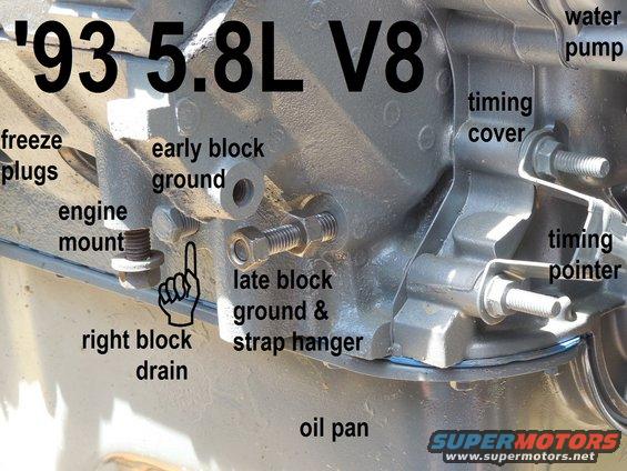
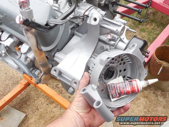
If you clean the alternator & bracket mounting surfaces, and the block ground surfaces; no, it won't be a problem.

blockgrounds9358.jpg


06bracket02.jpg
 
OP
OP
dmoses42

dmoses42

Contributor
Bronco addict
Joined
Jan 25, 2017
Messages
655
Loc.
Chatsworth, Ga
I'm not sure I understand the question, but the best configuration is the way Ford wired it on these latest 3Gs.
I guess a better way to ask it is, do I need to stick a ring terminal on the original yellow that I am disconnecting from the Voltage Regulator and also put it under the nut for the 175 amp fuse where the "new" alternator yellow/white wire is? Or do I cut the ring terminal off and use a butt connector and connect 2 yellows together and not attach it under the nut for the 175 amp fuse? But I think I have figured out that the yellow with the ring terminal was connected at the 175 amp fuse to get power, and the yellow from the original voltage regulator was supplying power, so I can either cap off the yellow from the voltage regulator and keep the ring terminal with the 175 amp fuse, or I can connect the 2 yellows (old vr and new alt wiring) together and not connect it to the 175 amp fuse. Am I on the right track? Thanks.

Don
 

DirtDonk

Contributor
Bronco Guru
Joined
Nov 3, 2003
Messages
51,621
I guess a better way to ask it is:
A. do I need to stick a ring terminal on the original yellow that I am disconnecting from the Voltage Regulator and also put it under the nut for the 175 amp fuse where the "new" alternator yellow/white wire is?
NO. In theory all you would be doing is connecting one end of an already powered wire, to another power source. So you'd have 12v+ at both ends and the wire would do nothing.
B. Or do I cut the ring terminal off and use a butt connector and connect 2 yellows together and not attach it under the nut for the 175 amp fuse?
NO/YES. But not yet!
Remember, you may have two, totally unrelated Yellow wires nearby. One of which is for the voltage regulator, the other for the horn relay. The two are separate and not really meant to meet. They can, but that's another story...
If I'm remembering correctly, you said you did have a horn relay. Correct?
But I think I have figured out that the yellow with the ring terminal was connected at the 175 amp fuse to get power, and the yellow from the original voltage regulator was supplying power, so I can either cap off the yellow from the voltage regulator and keep the ring terminal with the 175 amp fuse, or I can connect the 2 yellows (old vr and new alt wiring) together and not connect it to the 175 amp fuse. Am I on the right track? Thanks.
Just think of it like this, The ONLY thing you're doing at this point is connecting the battery to the alternator, I might as well confuse the issue more, by mentioning the TWO ways you're doing this,

One, and the most obvious, is the new larger cable with the big fuse, between the battery positive side of the starter relay and the BAT output terminal of the alternator.
That part you've got down. This is the main charge wire obviously.
The second connection is the Yellow wire we're talking about. This is the "system sensing wire" and tells the alternator's built-in voltage how much charge is needed to maintain the battery.

Don't cut anything until you have fully ascertained what Yellow wire you're messing with. The one on the old regulator should be spliced into the main harness Black wire somewhere under the factory tape, The horn relay has a ring terminal and is attached to the battery side of the starter relay. They are NOT the sane wire.

Is your battery connected? If so, you can test the Yellow wire from the voltage regulator to see if it's got battery voltage on it.
If not, then re-connect the Yellow wire with ring terminal to the starter relay and re-test.
When it's not connected, does your horn work? If not, reconnect it and test the horn again.

Ultimately, if everything is normal as the factory wired it, you will take the wire that you disconnected from the old voltage regulator and connect it to the new voltage regulator. Period, end of story, that's it. Done.

Paul

 

DirtDonk

Contributor
Bronco Guru
Joined
Nov 3, 2003
Messages
51,621
Or, another way to think about it, is like this.
No matter what color wire you choose, or where you choose to connect it, what you need/want to do is simply connect your new Yellow w/white wire from the new alternator's new internally mounted voltage regulator, to the battery.
If you choose to splice your old regulator's wire to the new regulator's wire, that's great.
If you choose to run a new wire from the new regulator connector, over to the battery positive cable, that's also great.
If you choose to do this via the starter relay, OR the new Mega-Fuse stud, either way is great.
If you choose to punt and just connect your new wire from the regulator, a few inches over to the BAT output post, that's not so great. But it works just fine in most cases. Which is why it seems that most people opt to do it that way.

And with all this back and forth, you can easily see why people default to just connecting the "A" terminal of the connector (Yellow w/white wire) to the "BAT" terminal of the alternator. Gets rid of headaches sooner.
But to my mind, if you can create a good solid weatherproof splice, then the best practice is to connect the old Yellow wire from the voltage regulator, to the new Yellow w/white wire of the new voltage regulator. Directly...

But in your case, first verify that the Yellow with a ring terminal is, or is not, the same as the Yellow from the old voltage regulator.

Paul
 
OP
OP
dmoses42

dmoses42

Contributor
Bronco addict
Joined
Jan 25, 2017
Messages
655
Loc.
Chatsworth, Ga
Or, another way to think about it, is like this.
No matter what color wire you choose, or where you choose to connect it, what you need/want to do is simply connect your new Yellow w/white wire from the new alternator's new internally mounted voltage regulator, to the battery.
If you choose to splice your old regulator's wire to the new regulator's wire, that's great.
If you choose to run a new wire from the new regulator connector, over to the battery positive cable, that's also great.
If you choose to do this via the starter relay, OR the new Mega-Fuse stud, either way is great.
If you choose to punt and just connect your new wire from the regulator, a few inches over to the BAT output post, that's not so great. But it works just fine in most cases. Which is why it seems that most people opt to do it that way.

And with all this back and forth, you can easily see why people default to just connecting the "A" terminal of the connector (Yellow w/white wire) to the "BAT" terminal of the alternator. Gets rid of headaches sooner.
But to my mind, if you can create a good solid weatherproof splice, then the best practice is to connect the old Yellow wire from the voltage regulator, to the new Yellow w/white wire of the new voltage regulator. Directly...

But in your case, first verify that the Yellow with a ring terminal is, or is not, the same as the Yellow from the old voltage regulator.

Paul
Well, I haven't cut, or actually even removed anything yet. The yellow wire I'm talking about is the one spliced onto the larger black wire that ends at the fusible link. Which is in fact still connected to the olld voltage regulator and radio noise suppressor. Apparently I don't have a horn relay, because there isn't anything yellow connected to my starter relay. The only thing yellow on that side of the engine bay is the voltage regulator wire.
 

Steve83

Bronco Guru
Joined
Jul 16, 2003
Messages
9,359
Loc.
Memphis, TN, USA, Earth, Milky Way
I guess a better way to ask it is, do I need to stick a ring terminal on the original yellow that I am disconnecting from the Voltage Regulator...?
No, that wire is dangerously undersized for any 3G. And its replacement exists completely in the later 3G harness, so it should be cut off very close to where it's spliced into the Bk/R wire, and capped. The original Y and VR connector are discarded.
Or do I cut the ring terminal off and use a butt connector and connect 2 yellows..?
If you mean the original noise capacitor - that's also discarded. The 3G VR has built-in noise suppression.
But I think I have figured out... Am I on the right track?
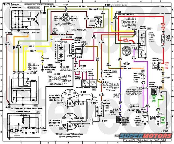
It doesn't seem so, but it's really hard to follow all of that text. The relatively-small Y to the VR powers the rotor. The VR detects voltage on that Y wire and reduces the voltage/current going into the rotor to reduce what comes out of the stator for charging the battery & powering the truck through the relatively-large alternator output wire (Bk/Y originally).

wiring7374apwrdstb.jpg


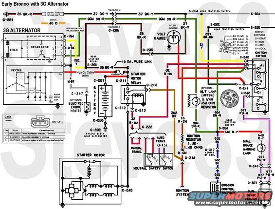
The 3G VR also uses the small Y or Y/Wh wire to sense system voltage, but it works on the ground side of the rotor to regulate the stator's output. Both monitor the Bk/Wh wire for diagnosis, but the early design also uses that as a 6V output for the old 6V choke heater. Both detect voltage on the LG/R wire to know when the key is in RUN, and both ground that wire to turn on the charge warning lamp.

3gswap.jpg
 

DirtDonk

Contributor
Bronco Guru
Joined
Nov 3, 2003
Messages
51,621
The yellow wire I'm talking about is the one spliced onto the larger black wire that ends at the fusible link. Which is in fact still connected to the olld voltage regulator and radio noise suppressor.
Ok, great. Leave it connected to the Black wire (which you will leave connected to the starter relay) and splice the end that you remove from the old voltage regulator, to the Yellow w/white wire from the new regulator.
Done...
Apparently I don't have a horn relay, because there isn't anything yellow connected to my starter relay.
Ok, I was probably just mis-remembering from another thread. At least that's my excuse for bringing up a horn relay, and I'm sticking to it!
Simplifies things. You only need to connect your old Yellow wire to the new Yellow wire.

Steve's comments about the wire being undersized were pertaining to the old Black wire from the back of the alternator. Not the old Yellow sensing wire.
But check out, and study his wiring diagrams. Even if you are uncomfortable with diagrams, his are pretty straightforward and include both standard and upgraded alternator scenarios.

Paul
 

DirtDonk

Contributor
Bronco Guru
Joined
Nov 3, 2003
Messages
51,621
No, that wire is dangerously undersized for any 3G. And its replacement exists completely in the later 3G harness, so it should be cut off very close to where it's spliced into the Bk/R wire, and capped. The original Y and VR connector are discarded.
Ok, so now I'm confused. I might be wrong about where the Yellow is spliced into the Black, but the Yellow itself is not undersized for simple sensing duties and can in fact be spliced into the new 3G regulator connector.
Where I might be wrong, is whether or not the Yellow (is that 152 in your diagram?) is spliced into the Black wire at the starter relay, or the Black wire coming from the alternator.
But either way, if the Black wires remain mostly intact, and that factory splice remains intact, then he can leave the splice alone, keep the Yellow wire as the sensing wire, and simply(?) connect the old to the new.

Yes, we don't want any of the old Black charge wire connected to the new alternator. But the Yellow is fine.
Not sure if you were thinking of the Black w/yellow when you said it was undersized, but that's what I took from your comment.

I notice that these diagrams are the '73/'74 version. Do you have the earlier version that would be more appropriate for his '72? A very late '72 might have some characteristics of a '73, but in general they are very different harnesses under the hood.
Where does it show the location of the Yellow-to-Black splice?

We are talking about your '72 here, right dmoses? If so, I spaced on the horn relay aspect and was definitely thinking of another discussion.

Paul
 

Steve83

Bronco Guru
Joined
Jul 16, 2003
Messages
9,359
Loc.
Memphis, TN, USA, Earth, Milky Way
I'm not clear on how he planned to use the old Y wire, which is why I said to cut it off & cap it. In any case - that entire function is served in the new harness, so there's no reason to connect the old Y wire anywhere (which might send too much current through it, so why risk it?).

The old Bk/R wire is what supplies all the old loads on the truck that are powered through the old fuse block & ig.sw. Changing the alternator has no effect on those, so no effect on current flowing through that wire (other than eliminating the charging current since the 3G output is connected to the battery at the starter relay).
 
OP
OP
dmoses42

dmoses42

Contributor
Bronco addict
Joined
Jan 25, 2017
Messages
655
Loc.
Chatsworth, Ga
Ok, lets start over.

This is on a 1972 Bronco.

Concerning the alternator:

Upon completion, the old 1g voltage regulator will be removed, along with its connector.

From the firewall comes a black wire (38) that ends at the starter relay, with a fusible link. Enroute to the starter relay, the yellow (152) splits off of it and goes to the voltage regulator. Looking at the schematic, it appears that this yellow from the old voltage regulator should be connected to the "A" post on the 3g alternator/regulator. Black wire with the fusible link (38A) stays connected to the starter relay.

Also from the firewall comes a Green/red wire (904A) that goes to the old voltage regulator. It appears that this wire should be connected to the "I" post on the 3g alternator/regulator.

On the 3g alternator/regulator plug, it has the white/black wire (4) that just loops over to the actual alternator.

From the old voltage regulator there is an orange wire (35) that gets removed.

The black/yellow wire (37) that goes to the 1g alternator "B+" post gets capped off. No longer used.

The Black/red (26) between the old voltage regulator and the alternator gets capped off. Mine doesn't have one, so there's that.

A new 4awg cable is connected to the "B+" post on the 3g alternator and goes to an inline 175 amp fuse, then on to the Positive side of the starter relay (C211).

New 4awg cable from the Battery post of the starter relay to the Positive battery post (C211 to C207).

New 4awg cable from Starter post of the starter relay to the starter motor (C212 to C245).

New 4awg cable from Negative battery post to a ground post on the engine block near the alternator(C206 to G202).

Brown wire (262) stays connected to the "I" post on the starter relay (C214).

Red/blue (32) wire stays connected to the "S" post on the starter relay (C213).

Am I missing anything? I used these two schematics for reference.

https://www.supermotors.net/registry/media/1100970_1

https://www.supermotors.net/registry/media/870470_1
 
Last edited:

Oldtimer

Contributor
Jr. Member with Sr. moments
Joined
Feb 4, 2005
Messages
1,795
Loc.
Sunnyvale, CA
New 4awg ground cable from Negative side of the starter relay to the starter motor (C212 to C245).
This NOT a ground cable.
It goes from the non battery side of starter relay to the starter motor, and is 12 volts, when key is in START position.
 
OP
OP
dmoses42

dmoses42

Contributor
Bronco addict
Joined
Jan 25, 2017
Messages
655
Loc.
Chatsworth, Ga
This NOT a ground cable.
It goes from the non battery side of starter relay to the starter motor, and is 12 volts, when key is in START position.
Yes, I misrepresented that one. Obviously if it is the only cable going to the starter it has to be part of the start circuit. Thanks for the correction. I will fix it in my previous post.
 
Top