• Welcome to ClassicBroncos! - You are currently viewing the forums as a GUEST. To take advantage of all the site features, please take a moment to register. It's fast, simple and absolutely free. So please join our community today!
    If you have problems registering or can't log into your account, please contact Admin.

Bandit's EDIS OBDII 351w Build

sprdv1

Contributor
REBEL
Joined
Mar 8, 2007
Messages
81,985
After swapping in a 351w, 4r70w, and atlas 2 a few years ago using a mustang injection set up I have never been able to track down a random stalling issue I was having. Coupled with the tuner not making time to finalize the tuning, I decided it was time for an explorer injection swap.

I purchased a 98 explorer from a fellow member (thanks ngsd) that had been wrecked and also sat in his dad's backyard for a few years. (I probably killed 50 daddy long legs haha) It started right up and we were able to load it on the trailer.

I got it home, pulled into the shop, up on the lift and blew it apart. I pulled the trans, and both harnesses. I wouldn't consider getting the harnesses out easy, I commend the people that do it in the junk yard, no thanks!

After watching EFI Guy's videos for a few dry runs while usually falling asleep on the couch, I took the laptop into the shop and starting cutting some wires. Since I had already installed a 4r70w that was an older case with the analog range selector, I had to do some extra pin swapping on the transmission connector as well as use two of the front o2 heater circuit wires, hopefully it works like it should!

Engine harness is pretty simple, I didn't end up opening any splices, I just snipped the wires and heat shrunk them. Lots of chasing wires all the way through the harness when de-pinning the ecm connector.

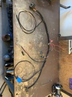
I got the firewall harness all split out into relay box side and into the cab side. I decided that I was going to try and use the black firewall connector to pass through the firewall. I de-pinned what I needed to, kept the wires I was saving and added the wires I needed from the other two firewall connectors, the brown and the gray. I haven't fully terminated yet so I can make sure my lengths are all correct.

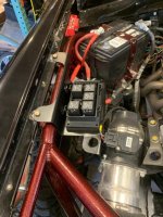
For the Relay/fuse box I decided to go with an amazon unit that seems pretty nice. I need to decide on a mounting position so I can get my wire lengths figured out get everything terminated.

I went to the junkyard and scored everything I wanted. I grabbed a Windstar ECM mount, as well as an Escape mount, and a spare 98 computer.

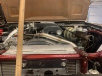
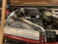
I decided on the fully enclosed Escape mount, I liked that the fact that I could fab up a bracket to hold the rear of the box up as well. Got the hole cut in the firewall which was a good time with the big 351 right in the way. Just waiting on my rivnut tool to arrive so I can mount it for good.

I am at a point now where I did have some questions that I couldn't quite pin down the answers to. I figured I would ask them here for others that might happen to run the same set up I have.

I have a centech harness that has the 10g yellow wire that I have been running on the battery + post of the explorer alternator for years. I had some of the mustang harness components loomed together with that part of the body harness. When I pulled the loom and tape away, I found a burnt up splice about a foot from the alternator ring terminal. From what I understand this was the incorrect place to put this wire with this alternator? This wire runs directly to the fuse panel. So with the explorer harness, if I wire up the alternator like Garry does with the short yellow wire fused from the plug directly to the B+ post of the alternator do I need the centech yellow alt wire?

Also in my body harness I have all of the sending unit wires hooked up to all my gauges in the dash. So if I were to hook up the single wire coolant temp, and oil pressure in the explorer harness and the wires from the centech harness that is just being redundant correct? You only need to use one or the other.

Here are all the pictures in sequence so far. Looking forward to driving this thing on the street without worrying if I can make that left turn in time or not!

Look forward to seeing the progress....
 

ngsd

Contributor
Bronco Guru
Joined
Mar 2, 2019
Messages
2,613
I want to see this done! You were fighting those demons when I came to get those axles from you almost a couple years ago! Glad to see you put the explorer to good use. Good luck. After I finish my wiring nightmare maybe we can get these rigs out and enjoy them
 

904Bronco

Contributor
Bronco Guru
Joined
Sep 28, 2004
Messages
6,040
Loc.
San Martin, CA
I enjoyed the read so far...

I looked at the same fuse panel you are using, but decided to go with the one Garry has been using. I am doing a 96-97 Explorer harness, converting most connectors to 96 components, including 96 4R70W.

Did anyone answer the Centech yellow Alt wire question? The wire comes from the back side of the fuse panel and has a fuseable link. Centech says it will support a 100 amps Alt. But not a 130A Explorer G4. I typically make my own Alt harness with mega fuse, or repurpose the 96-97 Alt feed wire from the Explorer with the twin fuseable links from the factory.

Dirtdonk has always recommended repurposing the Centech yellow wire to power something, like say a headlight harness...
 

lars

Contributor
Been here awhile
Joined
Jun 29, 2001
Messages
3,195
Loc.
NorCal flatlands
I enjoyed the read so far...

I looked at the same fuse panel you are using, but decided to go with the one Garry has been using. I am doing a 96-97 Explorer harness, converting most connectors to 96 components, including 96 4R70W.

Did anyone answer the Centech yellow Alt wire question? The wire comes from the back side of the fuse panel and has a fuseable link. Centech says it will support a 100 amps Alt. But not a 130A Explorer G4. I typically make my own Alt harness with mega fuse, or repurpose the 96-97 Alt feed wire from the Explorer with the twin fuseable links from the factory.

Dirtdonk has always recommended repurposing the Centech yellow wire to power something, like say a headlight harness...

I can't answer the question either, but I did the same thing. Alternator feeds the battery and buss through a megafuse. Yellow wire is connected to that on the protected side. Has been working fine for 20+ (gasp) years.
 
OP
OP
BanditBronco

BanditBronco

Sr. Member
Joined
Jul 2, 2008
Messages
690
I enjoyed the read so far...

I looked at the same fuse panel you are using, but decided to go with the one Garry has been using. I am doing a 96-97 Explorer harness, converting most connectors to 96 components, including 96 4R70W.

Did anyone answer the Centech yellow Alt wire question? The wire comes from the back side of the fuse panel and has a fuseable link. Centech says it will support a 100 amps Alt. But not a 130A Explorer G4. I typically make my own Alt harness with mega fuse, or repurpose the 96-97 Alt feed wire from the Explorer with the twin fuseable links from the factory.

Dirtdonk has always recommended repurposing the Centech yellow wire to power something, like say a headlight harness...


I have the relay/fuse panel all figured out, thankfully I am only a text away from Tony at CEautoelectricsupply, he got me dialed in.

As far as the yellow wire goes, I had an idea of where I was going to put it. I wouldn't mind understanding it better though. Does it receive power at the fuse panel or does it power the fuse panel? If Lars says he has his on the protected side of his mega fuse, isn't that still in the high amperage circuit till it gets to the battery?
 

904Bronco

Contributor
Bronco Guru
Joined
Sep 28, 2004
Messages
6,040
Loc.
San Martin, CA
I have the relay/fuse panel all figured out, thankfully I am only a text away from Tony at CEautoelectricsupply, he got me dialed in.

As far as the yellow wire goes, I had an idea of where I was going to put it. I wouldn't mind understanding it better though. Does it receive power at the fuse panel or does it power the fuse panel? If Lars says he has his on the protected side of his mega fuse, isn't that still in the high amperage circuit till it gets to the battery?

It (Yellow Alt wire) receives power from the fuse panel, protected by a fuseable link.
 
OP
OP
BanditBronco

BanditBronco

Sr. Member
Joined
Jul 2, 2008
Messages
690
Where do I get tach signal from for the yellow "tach Sndr" wire in the centech harness that goes to my autometer tach?
 
OP
OP
BanditBronco

BanditBronco

Sr. Member
Joined
Jul 2, 2008
Messages
690
Finally have a little update. Getting parts back from Powder coat and installed. Finished up the inside harness, used mostly weatherpak connectors where I could so I can pull the harness out independently without too much hassle. Got a solid state drive put in my shop computer so it is running a lot better for tuning downloads on the SCT. Now to start getting everything buttoned up and move onto the first start up!
 

Attachments

  • IMG_5914.jpg
    IMG_5914.jpg
    121.7 KB · Views: 66
  • IMG_5913.jpg
    IMG_5913.jpg
    109.8 KB · Views: 60

DirtDonk

Contributor
Bronco Guru
Joined
Nov 3, 2003
Messages
49,463
Nice. Did you end up figuring out what to do with the Yellow wire? And what function it has in it's original form too?

I did not see it discussed, so I'll add a few points. In the Centech harness, the Yellow alternator charge wire and the Red power feed wire from the battery (or the starter relay more often than not) are just like the Ford Bronco harness and to be considered one single wire running between the battery and the alternator. Just like the original Black w/yellow stripe wire and the Black wire.
Yes, they terminate at the fuse panel in the Centech harness, but the function is basically the same.

So in it's original form, the Yellow wire alternately either sits there doing nothing, or it carries power from the alternator to the rest of the vehicle and charges the battery.
When the engine is running the Yellow wire takes 12v and whatever current is asked for, from the alternator and powers up the system. Then some of it is carried by the Red wire and charges the battery.
When the engine is off there is no flow on the Yellow wire as long as it's connected to the alternator. Once you disconnect it however, it can carry power from the battery (via the fuse box connection) to whatever it touches. Probably enough to use as a light-duty arc welder if you let it touch grounded metal!

When using a more powerful alternator you either eliminate that Yellow wire, or repurpose it as 904 said. Keeping it mounted to the starter relay or the battery or any other positive voltage connection (such as a power distribution terminal) can keep it safe for use later. Using it to power an aux fuse panel or distribution block is a good way to keep it in service. It just won't have anything to do with the alternator and charging the battery anymore. That's all left up to the new wiring you run between the alternator CHG post and the battery.

Keeping it on the alternator in addition to the new heavier cable is an almost acceptible practice, but I would not want to do that in case the new heavy cable ever comes loose or fails for whatever reason, the Yellow cable is now back to charging things and could be over-taxed under the wrong circumstances. Think, melt-down.

And in that light, it sure looks like your splice was overheated. Might have happened during the soldering and heat-shrinking process, or it might have been overworked by the alternator at some point in it's past.
The current will always follow the "path of least resistance" so in the presence of a working heavy cable, virtually all the current is passed through the larger cable. With only a minimal to no current passing through the smaller Yellow cable in it's original configuration. So not really sure how it overheated if you were always using it with the additional cable directly to the battery or starter relay. One of life's mysteries...

But back to the beginning, just think of the Red and Yellow wires as one big loop of wire connected directly to battery positive.

Paul
 
OP
OP
BanditBronco

BanditBronco

Sr. Member
Joined
Jul 2, 2008
Messages
690
Thanks for the clarification Paul, hopefully it will help someone in the future. There is lots of bits and pieces of that info around but nothing grouped together. I had recently installed a WH headlight relay harness that uses two not so sexy ring terminals directly to the battery, so I ended up cutting them off and splicing them to the yellow alt wire to feed them power. That way I can wrap it all up in my passenger side fender wire loom and be good to go. I confirmed that they worked with just battery power and the switch pulled so we are in business there.
 

DirtDonk

Contributor
Bronco Guru
Joined
Nov 3, 2003
Messages
49,463
Sounds like the perfect re-purpose for that wire. Way more than enough capacity to run the lights and a few other things, but from your description it's also tucked safely out of the way and should be able to do its job for the life of the vehicle.
Not sure if the Centech harness is like the original in this case as well, but the brake lights take their power from the headlight switch in the original layout.
 
OP
OP
BanditBronco

BanditBronco

Sr. Member
Joined
Jul 2, 2008
Messages
690
Getting down to the final details before first start up. Startup tune is downloaded onto the SCT, datalogging is set up, had to hook up power and cycle the key, fuel pump scared me, because it ran so long while priming. Took me a minute to remember it had to fill the new feed line. Stainless lines came out good, purchased everything through mcmaster and swagelock I highly recommend. Posted a couple pics of the old aluminum lines vs. the new stainless ones.

Took a page out of the Lars play book for the upper radiator hose, because of my custom coil bracket, the upper hose I was using rubbed the fan shroud, so I whipped one up out of stainless.

I need to double check but I believe all I need to do now is fill the cooling system do a final check over, and turn the key.
 

Attachments

  • IMG_5953.jpg
    IMG_5953.jpg
    110.6 KB · Views: 68
  • IMG_5954.jpg
    IMG_5954.jpg
    114.1 KB · Views: 71
  • IMG_6089.jpg
    IMG_6089.jpg
    98.6 KB · Views: 85
  • IMG_6088.jpg
    IMG_6088.jpg
    105 KB · Views: 94

lars

Contributor
Been here awhile
Joined
Jun 29, 2001
Messages
3,195
Loc.
NorCal flatlands
Nice. Flattery will get you everywhere, ha ha.

Which hood is that? Body lift? Some familiar looking parts in there, including that upper intake. I have a WH Highlander hood and a 1" body lift. It barely clears the TPS and it was an adventure in plumbing to get the t/b connected to the MAF/air filter without hitting.

I'm a fan of hard plumbing, yup. The Swage Lok fittings sure are nice, and I've used plenty, though these days, due to another even more expensive hobby, I use one of these and just flare the tubing for AN fittings.

Edit, I see 1" BL in your signature. Should have paid more attention.
 

nvrstuk

Contributor
Just a Bronco driver for over 50 yrs!
Joined
Jul 31, 2001
Messages
9,425
Loc.
PNW
... looking great, almost there!! Can't believe you didn't stay up all night to fire it up! lol

waiting for startup results! :)
 
OP
OP
BanditBronco

BanditBronco

Sr. Member
Joined
Jul 2, 2008
Messages
690
Nice. Flattery will get you everywhere, ha ha.

Which hood is that? Body lift? Some familiar looking parts in there, including that upper intake. I have a WH Highlander hood and a 1" body lift. It barely clears the TPS and it was an adventure in plumbing to get the t/b connected to the MAF/air filter without hitting.

I'm a fan of hard plumbing, yup. The Swage Lok fittings sure are nice, and I've used plenty, though these days, due to another even more expensive hobby, I use one of these and just flare the tubing for AN fittings.

Edit, I see 1" BL in your signature. Should have paid more attention.

My hood is a high country from WH, I had to drill and tap the top of the throttle body for a 90 degree brass fitting to get the hood to close enough. It still rubs a hole through the vent tube every now and then. That is the only thing holding it up enough from laying on the TPS. I had to stick with a mustang style TPS sensor because they use a pigtail harness not a direct plug in like the explorer style.

I honestly am really liking mixing aircraft and hot rod parts. I just ordered a defrost diverter valve from aircraftspuce the other day that I am going to rig up for a Bronco I am working on that has a boat heater in it. already made for cable operation to work with the stock knob; who would of thought. Tons of useful trinkets and correctly shanked bolts, can't go wrong.

... looking great, almost there!! Can't believe you didn't stay up all night to fire it up! lol

waiting for startup results! :)

Waiting on a 11/16 crows foot to tighten up the return line on the side of the fuel tank, with only a 1" body lift they are such a pain to get to. Should be here today. I am honestly kinda nervous and probably pushing it off and triple checking things I probably don't need to. Hopefully soon!
 

nvrstuk

Contributor
Just a Bronco driver for over 50 yrs!
Joined
Jul 31, 2001
Messages
9,425
Loc.
PNW
How much fuel in your tank? You mentioned your fuel pump had to prime for a while.

I remember dumping in a full 5 gal. on my first startup with EFI I had individual pickups in each corner of my modified tank and it also took a long time to prime. It quit pumping 1/2 way thru the first trip to town. :(

I think it must have been having a hard time priming with the 4 pickups as maybe one of the rear ones on the slope part of my tank weren't covered???

Anyway, put in MORE gas than you think you need when you first prime that pump.

Best of luck
 
Last edited:

lars

Contributor
Been here awhile
Joined
Jun 29, 2001
Messages
3,195
Loc.
NorCal flatlands
My hood is a high country from WH, I had to drill and tap the top of the throttle body for a 90 degree brass fitting to get the hood to close enough. It still rubs a hole through the vent tube every now and then. That is the only thing holding it up enough from laying on the TPS. I had to stick with a mustang style TPS sensor because they use a pigtail harness not a direct plug in like the explorer style.

The 1" body lift I installed 20 years ago was in fact only 3/4". At the time I didn't care. With that "almost a 1 inch lift" and a Highlander hood, I had issues with my 408 with the same Trick Flow manifold you are running. Basically identical geometry.

The Accufab throttle body I'm using was supplied with a vent tube that stuck up too high. I solved that by replacing it with a much more sharply bent tube that I scrounged from some long forgotten throttle body. It uses the same Mustang TPS and it was hitting.

I took a chance and bought a new 1" body lift from Wild Horses. Lo and behold, it was an actual 1" body lift. So, I installed that, and for good measure I reinstalled the large washers from the original body lift. Thus giving me another 3/8" of clearance. A pain to install but worth the pain, as now nothing hits, and the only issue the extra lift caused was having to readjust my clutch linkage.
 
OP
OP
BanditBronco

BanditBronco

Sr. Member
Joined
Jul 2, 2008
Messages
690
Okay, so I finally got to turn the key and crank this thing. Actually two Sundays ago. Currently where I stand is a crank no start. I sent some cranking data logs to the tuner but haven't heard back yet. I have a pesky fuel leak I am trying to fix for good on an NPT adapter, still haven't gotten a complete handle on it.

I don't show any open codes on why it won't fire off, any other easy diagnostic tricks I can try while I am waiting to see what the tuner tells me? I know previously on the OBDI mustang stuff they have a nice crank no start flow chart on what to check first etc.

I haven't manually checked spark or injector firing to be able to tell if I have anything going on or not. I would assume if I had an issue it would show up in the form of a code like "incorrect voltage to coil" or something.

I honestly don't even know if the computer is on and working and communicating as it should.

When I turn the key to the on position, I get correct fuel pump prime, you can hear the relay click and then it just cranks, hasn't stumbled or anything remotely close to catching. It to me, sounds like their isn't any spark at all.

I haven't blown any fuses and everything seems to be set up correctly. Any "must have" requirements for start up that I can confirm? Like must have voltage here, etc to double check that it isn't anything on my end?
 
OP
OP
BanditBronco

BanditBronco

Sr. Member
Joined
Jul 2, 2008
Messages
690
He is still doing them, last I heard he had a decent back log and was just going along at his pace. I chose to go a different route because I couldn't reliably get a hold of him without feeling like a burden. I used his youtube videos to build my harness, but he didn't tune my computer.
 
Top