• Welcome to ClassicBroncos! - You are currently viewing the forums as a GUEST. To take advantage of all the site features, please take a moment to register. It's fast, simple and absolutely free. So please join our community today!
    If you have problems registering or can't log into your account, please contact Admin.

burning up ground wires please help

Sniper

Contributor
Full Member
Joined
Apr 23, 2013
Messages
251
Loc.
Omaha Nebraska
i found out my alternator had gone bad when my bronco left me stranded at a friends house, luckily a jump got me home, anyways bought a new alternator and installed it aswell as a new battery, after a couple days it died again, bringing the old alternator in and talking to the parts guys i found out the PO jerry-rigged his own built in reglator and wiring, the new alternator needed an external regulator, so i got one and wired it to the specs i found online for fords and that came included with the alternator, upon starting i had a hell of alot of smoke coming from the engine bay and throwing it open with an extinguisher in hand i found i had completely burned up my new ground wire, after putting a 6 gauge wire inplace of the 16 gauge the parts dealer had given me from the alt ground to starter solenoid ground i tried again, once again smoke and this time the ground from the negative terminal to the side of the truck burned up and the 5 gauge main wire off the negative terminal had smoke coming from both, i'm at a total loss as to what i am going wrong.


i used this http://www.junkyardgenius.com/charging/ford02.html

i was told by the parts store rep that i didn't need to connect the I cable since i a bronco has gauges and not lamps.

the ground is running to the starter solenoid ground because it was easier to reach

i had the S cable running from the stator to the S terminal on the regulator

F to alt field

and A to alt battery terminal


i'm getting really scared to touch my truck with having smoke rolling out of it three tries in a row, but i can't get it to a mechanic to do it for me now that i am burning grounds without buying a $200 tow.
 
Last edited:

Viperwolf1

Contributor
electron whisperer
Joined
Aug 23, 2007
Messages
24,340
Your first mistake was using that other website diagram. It is for a charging system with an indicator light instead of an ammeter. Here is the correct diagram.

Also make sure you have a good ground cable and clean connections between the battery and the engine block.
 

Attachments

  • alt-reg.jpg
    alt-reg.jpg
    39.1 KB · Views: 61
OP
OP
Sniper

Sniper

Contributor
Full Member
Joined
Apr 23, 2013
Messages
251
Loc.
Omaha Nebraska
ok so


ground the alternator to the starter solenoid

F connect to field screw

S to the top of solenoid for 12v when running (i think the top is ignition)

A to battery port on alternator for 12v always? and battery port on alternator to battery +?

I unused

stator unused


also is it normal for the 4-6 gauge main wires off the terminals and ground wires to be very hot/warm to the touch when not running starting or idling, just connected to the battery?
 

Viperwolf1

Contributor
electron whisperer
Joined
Aug 23, 2007
Messages
24,340
Alt should be grounded to the block through mounting bolts. The ground you see in the diagram is to ground the alt and reg together so they have a common voltage reference.

"S" goes to 12V in RUN, not 12V in START at solenoid "S" or 6V at solenoid "I" terminal. You should have the original green-red wire there somewhere.

BAT to positive battery terminal is fine. Either can supply 12V to "A".
 

Jdgephar

Bronco Guru
Joined
Sep 25, 2012
Messages
1,344
Something doesn't sound right. Burning up a 6 gauge wire, and the large ground wires from the battery means your pulling some seriously high current where you should not be. When you talk about connecting the alternator ground to the "Starter solenoid ground", did you connect the alternator ground to the black wire on the starter solenoid, or the starter relay? That's not a ground! The solenoid for the starter grounds to the engine block through the bolts that attach it to the motor (if you have that style of starter, which is usually an upgrade). You most likely connected to the starter relay. The starter relay has no ground connection (other than for the operation of the relay, but that's low current, and don't use that as a ground). The large wires on the relay are both battery positive, and you'll short out the battery if you connect one of those to ground.
 
OP
OP
Sniper

Sniper

Contributor
Full Member
Joined
Apr 23, 2013
Messages
251
Loc.
Omaha Nebraska
do believe the ground from the alt was not properly grounded, i'll ground it to the block, re-wiring right now, need to find a 12v RUN wire somewhere

grounding to the engine block where the bat - bolts on should be fine right?
 
Last edited:

Viperwolf1

Contributor
electron whisperer
Joined
Aug 23, 2007
Messages
24,340
grounding to the engine block where the bat - bolts on should be fine right?

Yes, that's fine. Just make sure it's large enough to pass as much current as the alt makes.
 
OP
OP
Sniper

Sniper

Contributor
Full Member
Joined
Apr 23, 2013
Messages
251
Loc.
Omaha Nebraska
got everything else re-wired with new ground wire to replace the burned wire, just need to find a 12v while run wire.
 

Viperwolf1

Contributor
electron whisperer
Joined
Aug 23, 2007
Messages
24,340
got everything else re-wired with new ground wire to replace the burned wire, just need to find a 12v while run wire.

It's the green-red wire in this bundle.
 

Attachments

  • untitled.JPG
    untitled.JPG
    65.8 KB · Views: 67
OP
OP
Sniper

Sniper

Contributor
Full Member
Joined
Apr 23, 2013
Messages
251
Loc.
Omaha Nebraska
found it! thank you!

got it all wired up and started it, some fluid or tape residue was burning on the outside of the headers, but it's been running for 5 minutes straight no smoking or issues, i tried to test the alt and it seemed to have been putting out around... 18 amps i think and the battery was reading about 14

i think i have it hooked up right, but twice i had the power just completely stop, for no reason, and the engine died while idling, it happened before and i took it to a mechanic a few weeks ago and he couldn't figure it out and it just stopped doing it, this is the first time it's done it in a few weeks, i don't know what it is, but letting it sit for a couple minutes i tried it again and it started and has been idling for about 10 minutes now.
 

broncnaz

Bronco Guru
Joined
May 22, 2003
Messages
24,341
18v is to high Id say your regulator is bad and is allowing to much voltage. something like 14.5 is all you should be showing max.
Cant really tell you why it dies when idling it could be a number of issues. Bad wiring, Fried ignition, fuel system issue, to rich of a idle mixture. the list goes on.
 
OP
OP
Sniper

Sniper

Contributor
Full Member
Joined
Apr 23, 2013
Messages
251
Loc.
Omaha Nebraska
it dies when idling due to a total power loss somehow, all power to all instruments starter everything goes when it dies like that
 

Jdgephar

Bronco Guru
Joined
Sep 25, 2012
Messages
1,344
Ignition switch going bad, or overheating maybe? Could be a dirty battery post connection if absolutely nothing gets power when it shuts down.
 
OP
OP
Sniper

Sniper

Contributor
Full Member
Joined
Apr 23, 2013
Messages
251
Loc.
Omaha Nebraska
i think it was the ground wire running from bat - to the body, i replaced the wire and the battery connector on the battery wire and scraped the area away with a wire brush and put a new bolt on it, i think that took care of it,

seems i still wired the alternator wrong, it's creating voltage but not getting to battery.

this is the alternator i am using, does the A wire from the regulator go to the unlabeled screw at the top of the image showing the back of it?
 
OP
OP
Sniper

Sniper

Contributor
Full Member
Joined
Apr 23, 2013
Messages
251
Loc.
Omaha Nebraska
the 12v on run is a brown and green wire

i had it set to

12v on run to S terminal

12v constant to A terminal

field to F terminal

and it didn't work

right now i have


STA to S terminal on regulator

field to F terminal

ground to engine block from right ground post next to field post

12V while RUN to I terminal on regulator.

12v constant from alt battery terminal to A

wire running from alt battery terminal to starter solenoid positive side (touching bat positive wire)

i am so confused as to why it isn't working.

this is the 1g alt i have

http://www.tuffstuffperformance.com/pdf/7078_Custom_Alternator.pdf
 
Last edited:
OP
OP
Sniper

Sniper

Contributor
Full Member
Joined
Apr 23, 2013
Messages
251
Loc.
Omaha Nebraska
i'll try moving the ground that goes from the ground post on alt from the engine block to going from the alt to the bolt holding the regulator to the wheel well
 

Viperwolf1

Contributor
electron whisperer
Joined
Aug 23, 2007
Messages
24,340
That's a strange alternator setup. I suggest calling the manufacturer.
 

DirtDonk

Contributor
Bronco Guru
Joined
Nov 3, 2003
Messages
48,109
Well Demon, while everyone else is pulling themselves back off the floor from the shock, I'll see if I can help.
I was going to say there should be no confusion as to why it doesn't work, because you were wiring it wrong. But with this new alternator being a non-Ford type (the reason for the previous shock) the way you have it now might actually work.
Since it doesn't, I'm going to have to say that the worst case is that your new alternator might have gotten fried in all the excitement.

I'm just wondering though, why it took two days and 16 posts before you mentioned that you've got a CUSTOM HYBRID ALTERNATOR that doesn't even remotely resemble a stock Ford type that you're using as your wiring theme?
That info would have been very helpful at the first sign of melting wires.

You don't mention it's output either I don't think. But if my search is correct, this is at least a 100 amp alternator. I see you're trying to run it through a new wire straight to the starter relay post, but what gauge is it?
It should be at least 8ga just for beginning, but could be as big as 4ga without being too much overkill. 6ga seems to be a happy medium, but using anything like 10ga or smaller might work for a short time, but could explain some of the smoke under the hood too!

What did you do with the old Black w/yellow wire from the BAT post on the alternator?
Hopefully it's safely taped up, wrapped up, tied off, or otherwise put somewhere safe.
As long as the original Black wire is still attached to the starter relay with the battery cable and your new charge wire, the end that used to be attached to the alternator is powered up hot all the time.

Ok, sorry I'm being pissy tonight. No excuse and I apologize. It was just a shock to realize what you're working with. And diagrams that are so far removed from what a stock Ford truck with gauges utilizes.
Even though they might work for your new one, nobody would know because they would not work in a typical EB setup.

So now back to the bad news. If it doesn't work after the next time Viper replies and clears up what I say next (in case I'm wrong), you should probably try to have it tested to make sure it's even still working. With so much smoke and incorrectly connected wires at this point, it's very possible that the alternator is now fried and won't work no matter how you hook it up.
Sorry to bring bad news into the mix before you try it more ways, but it's a possibility that needs to be mentioned.

I would think any auto parts store could test it, but they'd have to use older GM jumpers and methods, rather than Ford. An experienced tester should be able to see right off that it's GM based though.
But you might just call RuffStuff anyway, to clarify how to test it. Just in case.

And also tell them that their drawing you posted a link to is likely giving out incorrect info, at least as far as the trucks of this vintage are concerned.
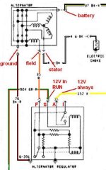
For our trucks, the "F" or Field wire is ALWAYS Orange, the "STA" or Stator wire (when present) is always White w/black and there is no Green wire on the back of the alternators in these applications.
Again, maybe that's true of cars, and vehicles of other vintages, but no wiring diagram I have shows a Green wire to the FLD terminal.
Even if true for some, they should at least mention the possible variations and acknowledge that if you melted your new alternator, that it should be covered under warranty due to the confusion regarding their colors and locations.

I'm a total fan of TuffStuff by the way. Full disclosure says that I even used to be a sales rep for them for a short time (too short in my opinion) several years ago.
Liked their product, liked them personally, and thought they had some good ideas for this type of hot-roddy stuff.

I don't see where you mention it, but did you note in Step 5 of the instructions that if there was no S wire on your old alternator, you don't use one on the new one either?
Even though their diagrams show that one should have been present, and they have no way of knowing that your wiring is hacked, they did mention the possible differences.

As mentioned, your entire electrical system dying may be due to the old charge wire deteriorating from the partial meltdown. If the grounds were smoking, there's a chance that some of the positives were too.
Check the condition of the inline butt-connector behind the ammeter in the instrument cluster. If that one corrodes, melts, or just comes loose, you could lose all your power like you were experiencing.

So, to reiterate what Viper and the diagrams said, plus what I now think they should be with your new alternator.
Using "Bronco" standards:

1. Orange Field wire from F of the regulator to the terminal that they tell you to put it on in their new plug. Orange-to-Green then, it sounds like.
2. NO S wire on the new alternator.
3. Green w/red stripe of your old harness to S terminal of regulator.
Not sure what the Brown w/green wire is. Not one on a Bronco that I'm aware of. But as long as you test it for 12v with the key on only, you should be good.
How badly hacked is this from the PO? Could it have had new wires put in? Or could those colors be altered as a result of all the heat?
Just wondering.
4. Yellow wire in stock harness to "A" of regulator.
5. No "I" wire to regulator.
6. Ground wire from any GRD stud or any case bolt of the alternator to one of the bolts holding the regulator to the body.
Leaving your ground wire to the block is fine, but it's important that the original ground scheme be retained. And that's, as Viper said, from the alternator to the regulator so that they have the same ground potential.
7. You may have to test the new regulator too. Not sure if it could have fried in all this, but anything is possible. And if you ever attached power to it before it was bolted to the body, it could be fried.

If that doesn't work, we'll go through it again with the wiring methods that they are using in their instructions.
I know you've already done it both ways in theory, but with the slight variations it seems like you put in, would you mind trying it again? This time as written above first. Then if it doesn't work, we'll run down the other way. I'm not adding it here because my posts are always confusingly wordy anyway. So I'll leave it for another time, in case it's even needed.

Hope that gets it working.
I'm on your side still (even if it doesn't sound like it). I had to re-write it like fourteen times! Just to change the tone and to correct some of my mistakes from not reading your last post thoroughly the first time.

Good luck.

Paul
 

DirtDonk

Contributor
Bronco Guru
Joined
Nov 3, 2003
Messages
48,109
And since you're still here Viper, have you ever seen a truck wired up like the non-ammeter method after a voltmeter was installed?
Any reason you can think of that it would not work?

I'm just thinking out loud. I was first writing that it can't work here, because that's now how Broncos are wired. But after thinking about it, once you bypass the ammeter loop and go to a voltmeter, what's to stop you from using the other wiring scheme that Ford used on idiot-light vehicles?

Paul
 
Top