• Welcome to ClassicBroncos! - You are currently viewing the forums as a GUEST. To take advantage of all the site features, please take a moment to register. It's fast, simple and absolutely free. So please join our community today!
    If you have problems registering or can't log into your account, please contact Admin.

OBD II Engine/Transmission Swap - The Next Generation

Dave

Contributor
Bronco Guru
Joined
Aug 25, 2006
Messages
2,262
I'm starting this thread to document on going work and share information as I go. I know that these conversions have been done but there is not much information available.

I found a 2000 5.0L/4R70W AWD Explorer with a clean engine and 101,000 miles.

Update: Pulled the plugs and they looked like 101,000 miles but were very uniform in the burn color for a healthy engine. Cold compression was 135 on every cylinder at 8 revolutions. Very uniform. This is one reason to choose these newer engine that ended up in the salvage yard due to closisions.

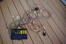
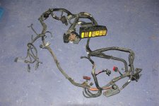
I got the engine, transmission, computer, harness, and all of the other parts that might be needed for $500 + tax. I had been looking for a AWD without active suspension to keep things simple(r). AWD and 2WD to not have all of the traction and shift control functions that exist in the 4WD versions.


Update: It appears that all of the transfer case shift functions in the 4WD Expolrers are handled by the GEM (Generic Electronic Module) which doesn't effect the PCM and it shift functions of the 4R70W. That module is not being used so it shouldn't matter if the donor is a 2WD AWD or 4WD. Active suspension should not present and complications either. I won't be able to absolutely verify that without actually going through a 4WD. Using the Explorer electronic transfer case would be a bit of a challenge. The GEM uses inputs from the front and rear ABS speed sensors and monitors several other functions to control shifting a traction control. The good news its that it doesnt effect the PCM.

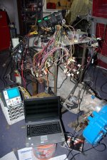
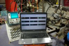
I'm using Alldata as my source for the electrical diagrams etc. Very complete information but it takes a little while to find your way around.

I'll post and edit entires as I systematically go through the process.

Please feel free to add any helpfull information.

Thanks, Dave...
 
Last edited:
OP
OP
Dave

Dave

Contributor
Bronco Guru
Joined
Aug 25, 2006
Messages
2,262
Anti-Theft Systems

So far it apears that tha passive anti theft system (PATS) is the only thing that prevents the Powertrain Control Module (PCM) from running unless it can read the chip in the key. I pulled the PATS module and the key reader module. Pretty simple 4 wire interface between the two. The PATS communicates to the PCM via the data bus which is a two wire connection. The PATS module is keyed to the PMC so you need both modules out of the same vehicle.

The PATS module is mounted behine the passenger side airbag. Two bolts that are accessable from the roof of the glove box hold airbag in place. Follow the safety instructions for removing an airbag. The key reader is accessable by popping the bottom molding off the stearing column and removing one screw. Cut the wires on the far side of the connectors. The PATS communicates to the PMC by those two twisted wires which are also connected in paralell to ot the OBD II connector. The remaining wires from the PATS are hot always, hot in run, ground, and the theft light on the dash. Should make a nice security system for the Bronco.

There are actually 2 information busses. SPC which is the basic OBD II comunications and ISO (or CAN) which talks to all of the other modules (7). Only the SPC should be required to talk to the PMC and and provice communications between the PMC and PATS.


Alldata has nice diagrams of the connectors and wiring diagrams.
 

Attachments

  • IMGP0003 (Large).JPG
    IMGP0003 (Large).JPG
    41.7 KB · Views: 270
Last edited:

B_lineBronco

Jr. Member
Joined
Jan 15, 2007
Messages
104
Loc.
Red Bluff
I really look forward to following your thread on this. While I am still looking for the "right" Bronco, I have been looking for a used explorer that can be used as a dd for a while, so that I can then strip all the parts for the future Bronco (this all sound more plausable when explaining to my wife)...
 

Explorer

Bronco Guru
Joined
Mar 2, 2008
Messages
4,390
Loc.
Raphine, Virginia
Great project idea. But thats why I work on the old stuff, at least when things go bad, I can usually fix it. Most advanced thing on mine is the Duraspark. Thinking about changing that to points.
 

Broncobowsher

Total hack
Joined
Jun 4, 2002
Messages
35,121
I am not saying it can't be done. But it is a lot of work. It sounds like you are on the right track. Starting with a whole running truck is a good start (way better then those who get an engine, harness and computer and nothing else from a boneyard).

I have done a couple late model swaps. But it was late model into late model and there was a lot of parts already there that interchanged (complete fuel and evap systems for example). A quick cheat for the PATS is to stick the key in the lock cylinder with the reciever module still attached. then zip tie the whole mess up under the dash. When ever it checks for a chip in the key, it sees it and is happy.

The wheel speed sensors for the traction control will be interesting, let us know how you pull that one off.
 
OP
OP
Dave

Dave

Contributor
Bronco Guru
Joined
Aug 25, 2006
Messages
2,262
The wheel speed sensors for the traction control will be interesting, let us know how you pull that one off.

The ABS generates a signal from the wheel sensors. It's a single wire to the PMC. The pulse rate and signal properties look very similar to that generated by a VSS.

It might be less work and cleaner than most think if some good ground work is done. We shall see.
 

eric0o1

Sr. Member
Joined
Apr 17, 2008
Messages
592
In my own personal experience with electrical diagrams, using Alldata for a source of technical information usually ends up comming back to bite me. I would reccomend trying to find the Ford shop manuals for a 2000 explorer. Alldata has a tendency to just copy diagrams over from the previous year, not knowing about the small changes made from year to year. Shop manuals can be expensive, but can easily be resold. Of course in your case All Data could be 100% on all the info you need. I just thought I'd share my experience and opinion
 
OP
OP
Dave

Dave

Contributor
Bronco Guru
Joined
Aug 25, 2006
Messages
2,262
Electrical Harness

The electrical system in the Explorer is layed out in a much more modular manner than the older OBD I systems. The part of the harness that I'm concerned with is all self contained on the engine and contains the PCM. It provides all of the engine and transmission controls and sensors which are connected directly to the computer unlike the OBD I systems where we have to provide the harness between the computer and all of the controls and sensors. There is a large connector on the rear top of the engine (pic 1)that ties this whole system into the rest of the vehicle. One small connector at the front drivers side of the engine contains the start signal, A/C clutch, oil level, and oil temp which are not monitored by the computer.

(I'll include wire colors and diagram references and connector numbers later)

The large connector provides power to the PMC, a few external sensors and controls, field power to the alternator, and bus communications. I'll have a complete list as I go. Several of the wires from this connector go directly to the power distribution box.

The power distribution box is a very nice module that will make the instalation very clean and convenient (pic 2). It has a very nice mounting bracket that will bolt right up to the inner fender just like in the Explorer. It connects directly to the battery, and alternator cable. It provides a 175 amp Mega fuse between the battery shown in pic 3. Don't freak out about picture 4. I pulled the box apart to trace each circuit. That will not be required once a colorcoded of the required circuits is generated.

The power distribution box contains the hot always power to the vehicle via fuses and relays. The important ones for now are the PCM power and relay, fuel pump power and relay, starter relay and alternator field power, and the air conditioning clutch relay (keeping it intact just in case). No modifacation or cuts yet. There are also some fused and relay controled circuits that will be available for the rest of the vehicle. They include a blower relay, horn relay, rear window, sun roof, rear wiper, etc. Ill use them for my headlights, driving lights, horn, and still have some spares. It should be capable of providing fused circuits for all of the Bronco's circuits.

The last picture is of the battery junction box and engine compartment wire harness. Most of the connectors and circuits will be removed. More later:
 

Attachments

  • IMGP0001-1 (Large).JPG
    IMGP0001-1 (Large).JPG
    114.3 KB · Views: 466
  • IMGP0002-1 (Large).JPG
    IMGP0002-1 (Large).JPG
    95.8 KB · Views: 401
  • IMGP0003-1 (Large).JPG
    IMGP0003-1 (Large).JPG
    73.4 KB · Views: 340
  • IMGP0004 (Large).JPG
    IMGP0004 (Large).JPG
    112.5 KB · Views: 389
  • Wire harness 005 (Large).jpg
    Wire harness 005 (Large).jpg
    104.8 KB · Views: 310
Last edited:
OP
OP
Dave

Dave

Contributor
Bronco Guru
Joined
Aug 25, 2006
Messages
2,262
Fuel System

The 2000 Explorer has a returnless fuel system. It utilizes a pressure regulator in the tank which basically returns fuel directly inside of the tank. The single line runs to the engine fuel rail. A fuel pressure transducer on the fuel rail signals the PCM which controls the injector signals based on the fuel rail pressure. This is different from the return systems which relay on a pressure regulator that uses manifold pressure as a reference on the fuel rail with a return line to the tank and an assumed pressure by the PCM. The returnless system uses ivory colored injectors that have the same flow rate as the earlier system with the exception that they run at a rail pressure of 55 to 65 psi instead of 35 to 40 psi. In both cases the PCM outputs a signal to the fuel pump relay which energize the pump via the inertia switch. Very similar to the OBD I systems. The vapor management uses a tank pressure (and maybe temp) sensor, a vapor purge solenoid and canisters in the rear of the vehicle, and a vacuum solinoid in the front driverside of the engine compartment. It functions by venting the tank into the intake plenum just like the PCV system. The PCM controls these functions. I'll update this in detail as I progress.
 
Last edited:

old number 8

Jr. Member
Joined
Aug 6, 2007
Messages
134
Loc.
NOT Seattle
Sorry for the late post

So far it apears that tha passive anti theft system (PATS) is the only thing that prevents the Powertrain Control Module (PMC) from running unless it can read the chip in the key. I pulled the PATS module and the key reader module. Pretty simple 4 wire interface between the two. The PATS communicates to the PCM via the data bus which is a two wire connection. The PATS module is keyed to the PMC so you need both modules out of the same vehicle.

With PATS, there is a pickup sensor at the ignition tumbler. If you get it, and mount a key chip to it, you can mount the pickup anywhere. The down side to this is you need 2 keys programmed to activate PATS, and if you loose the programming to the one key, you must access the pickup to programm 2 keys to enable start. PATS is a very good anti-theft system, so I would advise using the entire system.

Just my opinion,
 
OP
OP
Dave

Dave

Contributor
Bronco Guru
Joined
Aug 25, 2006
Messages
2,262
With PATS, there is a pickup sensor at the ignition tumbler. If you get it, and mount a key chip to it, you can mount the pickup anywhere. The down side to this is you need 2 keys programmed to activate PATS, and if you loose the programming to the one key, you must access the pickup to programm 2 keys to enable start. PATS is a very good anti-theft system, so I would advise using the entire system.

Just my opinion,

Thanks, keep those ideas comming. I trying to come up with a sexy way to mount the key pickup with the ignition switch on the dash and use the explorer keys. I might also use the explorer electrical switch assembly actuated with an arm from a door key cylinder assembly. Still pondering that one.
 
Last edited:
OP
OP
Dave

Dave

Contributor
Bronco Guru
Joined
Aug 25, 2006
Messages
2,262
Transplant Parts List

The following are the parts required to make this whole system work (so far)

1. Complete engine and transmission assembly.
2. computer
3. Wire harness from engine connector to firewall connectors which includes the power distribution box. You can cut the harness just forward of where the wires split go to the horn and vapor solinoid in the lower drivers side of the engine compartment.
4. Vapor control solinoid valve and (horn - if you want)
5. Fuel pump/sending unit assembly (cut pig tail on connector)
6. Vapor canister assembly in rear of vehicle (Cut pig tail on connector)
7. Pats module located behind passenger side air bag. 2 bolts from roof of the glove compartment remove the airbag. Be carefull with it. (pig tail contecor)
8. Key reader and keys (PITA if but not a show stopper if the keys are missing). remove top and lower covers on stearing column. 1 bolt removes it from around the key cylinder. Get both sides of the connector.
9. Air box. I'm going to move the battery to the drivers side and mount the explorer airbox in the origional battery position.

(I'll include some picture later)
 
Last edited:

Ryan

Sr. Member
Joined
Aug 29, 2003
Messages
739
Loc.
Lansing, MI
1) Are you going to run cats and all 4 HEGO's?
2) What are you going to do about the FTP system?
3) The PATS system in delicate, I've seen people break the signals just by handling it wrong.
4) Same goes for the FPDM, not something to be messed with if possible.
 
OP
OP
Dave

Dave

Contributor
Bronco Guru
Joined
Aug 25, 2006
Messages
2,262
1) Are you going to run cats and all 4 HEGO's?
2) What are you going to do about the FTP system?
3) The PATS system in delicate, I've seen people break the signals just by handling it wrong.
4) Same goes for the FPDM, not something to be messed with if possible.

I'm running a stock exhaust system, with some mods to fit, up to the muffler including the cats and HEGOs.

I'm setting my fuel tank up like the explorer tank with the complete evap system which shouldn't be too obtrusive.

The 2000 5.0L uses a fuel pump relay and single speed pump just like the older systems. Unless I've overlooked something. I know it doesn't have fuel pump driver module that talks on the SCP bus. I beleive those are used on the modular engine models which use a PWM drive and variable speed pump.

Thanks for the heads up. Progress is a little slow right now due to a compromise. "You can buy that explorer if you put hardwood floors in the livingroom and bedroom."
 
Last edited:

Ryan

Sr. Member
Joined
Aug 29, 2003
Messages
739
Loc.
Lansing, MI
Sounds like you're doing good, and willing to tackle the job. We get make calls from people crying; "we welding in this newer motor, now what........?" You seem to be ahead of the curve.

Make sure you have a backup plan in case something doesn't work. I've made $1000+ custom EFI harness for people who didn't have a plan. They claimed to have the skills needed to reprogram the computer. When it failed, they had to spend more money to convert back to 93 Mustang EFI system.

Can you post a picture of the PCM for this project?
 
OP
OP
Dave

Dave

Contributor
Bronco Guru
Joined
Aug 25, 2006
Messages
2,262
Progress Report:

Got busy with a remodeling project and had to put the conversion on hold for a bit.

Today I applied power to the whole system in the test stand and hooked up my scan tool. Everything is talking and the key on engine off test passes. Tonight I'll try to clear the PATS keys and program a new set of keys. Once that is done I should be ready to hook up some fuel and fire it up. That will probably be after Christmas as we leave on a road trip spend the hollidays with the family back in Michigan.

That rats nest of wires isn't as intimidating as it looks as most of them are not used. Lots of available fused circuits and relays available. The complete harnes between the PCM - engine - transmission - and power distribution box are not touched. The only networked component required is the PATS (passive Anti Theft System) for the 5.0L. The vehicle would normally get vehicle speed information from the ABS. The speed siganl is compatable with a VSS which I'll be using. I'm learning a bunch and will pass it on.

I set the scope up to look at the communications between the PCM and the PATS just to see if they were talking.
 

Attachments

  • IMGP0001 (Large).JPG
    IMGP0001 (Large).JPG
    96.3 KB · Views: 339
  • IMGP0003 (Large).JPG
    IMGP0003 (Large).JPG
    96.5 KB · Views: 246
Last edited:

DirtDonk

Contributor
Bronco Guru
Joined
Nov 3, 2003
Messages
48,104
Other than it possibly being harder to adapt than overcome, what would be the downside to making the existing ignition switch work on the Bronco? Seems that having the key sensor integrated into the rest of the Bronco would be worthwhile.
Other than the reliability issue I guess. I'd sure hate to be out on Black Bear or Imogene Pass or somewhere equally far away from a FND (friendly neighborhood dealer) when the switch and the key decided to stop speaking to each other!
Keep the pics coming. We like seeing someone else buried hip-deep in wires too!

Paul
 
OP
OP
Dave

Dave

Contributor
Bronco Guru
Joined
Aug 25, 2006
Messages
2,262
The PATS system seeme to be pretty reliable as it is used on a lot of Fords. I dont think it will be any more suceptable to failure than any EFI system with a computer. The key reader is a bezel around the key cylinder. It might be possible to use the stock ignition switch with the reader mounted in the dash. One issue with the stock switch with the computer on OBD I or II is that you need a hot in run that is not cut off in the start position. Not hard to overcome but an issue.
 
OP
OP
Dave

Dave

Contributor
Bronco Guru
Joined
Aug 25, 2006
Messages
2,262
Battery Junction Box

The battery junction box is integral to the PCM harness. I plan on mounting it on the inner fender well and top of the wheel well with the Explorer mounting bracket. The battery will be moved to the drivers side with the airbox/MAF sensor in the origional battery position.

The Explorer, like most newer vehicles, has two wires running from the positive post on the battery. One directly to the starter and one to the battery box. The alternator feeds the battery box through a 175 Amp Mega Fuse. This provides a hot battery bus with 10 maxi fused and 14 mini fused circuits. It also provides 10 relays and two diodes to prevent back powering for circuits that are powered from multiple sources (i.e. lights that are powered from the switch or alarm system).

Only a few are required to run the system:

1. PCM power fuse, diode, and relay
2. PCM memory
3. Fuel pump fuse and relay
4. Starter Relay
5. Generator field fuse
6. Transmission, HO2S, CVS, EVR fuse.

Most of these are untuched in the harness. Wires to the battery junction box are only to the PCM relay (hot in run and start) , Starter Relay (hot in start), and from the fuel pump relay to the inertia switch and fuel pump. Basically 3 wires to make it run.

The rest are available for other uses. I'm using the Ignition fuse to power the ignition switch. The following fuses and relays are available to be reassigned:

1. power windows - 50 amp maxi
2. Abs pump - 60 amp maxi
3. blower motor - maxi and relay
4. centeral junction box - maxi
5. Air suspension - maxi
6. air suspension - maxi
7. 4 wheel drive - maxi


1. ABS control - mini
2. horn - mini and relay
3. heated seats
4. rear defrost
5. drl and fog lamps
6. rear wiper - and up relay, down relay, park relay, and high/low relay.

These represent the mass of wires in the picture in the previous post.

The A/c clutch fuse and relay are going to be kept for possilbe future use.

Under Construction

There are absolutly no modifications required to the engine/transmission harness which includes the PCM. This harness interfaces to the vehicle through 2 connectors. The first is a large block connector that branches to the battery junction box and the following remotely mounted components.

(rear of vehicle)

1. Fuel pump (via inertia switch)
2. Fuel tank pressure sensor
3. Fuel level sensor
4. Vapor vent solinoid
5. Vehicle Speed sensor (VSS)

(fornt of vehicle)

6. Brake position switch
7. Overdrive lockout switch
8. Vapor purge solinoid
9. PCM on (hot in run/start)
10. Tach
11. Oil pressure
12. Temp
13. Milfunciton indicator (engine light)
14. Transmission fault indicator
15. Charge via battery light (hot in run)
16. Ground

(I'll add the wire colors some diagrams soon)

The following circuits are unused and available as fused circuits form the battery junction box:

1. YE/LG Maxi fuse 3 available
2. RD Mini fuse 7 available
3. LB/WH Mini fuse 2 available
4. TN/WH Mini fuse 11 available
5. RD/LB Mini fuse 4 available
6. DG/YE Maxi fuse 8 available
7. TN/BK Maxi fuse 1 available
8. LB/PK Maxi fuse 9 available

The A/C clutch relay and fuse is also contained in the battery junction box. I'm going to retain this function for possible future use as an onboard air compressor.

5 Other fuse powered relays are also available for use for switched items such as the heater blower, lights, or any other high draw items. I'm going to use one fo the lights, blower motor, and horn and mayby a transmission cooler fan. That will be up to your imagination.
 
Last edited:
OP
OP
Dave

Dave

Contributor
Bronco Guru
Joined
Aug 25, 2006
Messages
2,262
Passive Anti Theft System operational

Just got home from Christmas with the family in Michigan and got back to work on the ODB II project. Got the PATS programmed today with 2 new keys. Not having a programmed key available made it more of a challenge than it had to be as the Auto Engineuty scan tool had some timing problems in its security access functions. I finally ignored the access refused message and it accepted the two keys. I've got spark and an engine waiting for fuel. Tomorrow I'll get a tank hooked up and hopefully a test run.

Note: The entire communications network consists of 2 wires that run from the PCM to the PATS with the Data Link Connector hooked in paralell. The PATS has 4 wires that run to the key reader through a connector, Hot always, hot in run, ground, and an output to a LED (theft indicator). Much easier to wire up than most aftermarket immobilizers and alram systems. I'll include wire diagrams later.
 

Attachments

  • IMGP0001 (Large).JPG
    IMGP0001 (Large).JPG
    68.2 KB · Views: 118
  • IMGP0003 (Large).JPG
    IMGP0003 (Large).JPG
    89.2 KB · Views: 142
Last edited:
Top