• Welcome to ClassicBroncos! - You are currently viewing the forums as a GUEST. To take advantage of all the site features, please take a moment to register. It's fast, simple and absolutely free. So please join our community today!
    If you have problems registering or can't log into your account, please contact Admin.

OBD II Engine/Transmission Swap - The Next Generation

OP
OP
Dave

Dave

Contributor
Bronco Guru
Joined
Aug 25, 2006
Messages
2,245
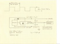
First thought to that is use an octocoupler (optical coupling) On the positive side of the waveform it turns on, negative it goes off. Limiting curcuits to keep from overloading the driver as needed.


I'm going to put a digital scope on the ABS VSS output on the 98 Exporer today and see what the signal looks like. I'll then do the same on the 94 Mustang conversion VSS. If I dont have to do anything with pulse count there is a chip available from MAX for reading VRRs in automotive applications.

I'm going to stop by the junk yard and grab a mechanical passthrough VSS and a ABS module to disect and see what Ford used.

I've been told that there is a module available to convert a VSS signal on older vehicles to digital pulses for the purpose of driving devices that use vehicle speed such a taxi cab meters, sound systems, nav systems, etc. Still searching.

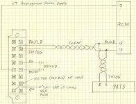
Update: A little research on speedometer calibration showed that 1000 rpms is 60 MPH. Tapped into the VSS signal at the radio on my 98 Explorer. The ABS puts out a pretty clean digital pulse stream. Seems to comply with the industry standard of 8000 pulses per minute at 60 MPH. (8 pulse per revolution VSS turning at 1000 RPMS) I picked up VSS and speedo cable at the junk yard that fits in the D20. It was out of a 91 Explorer. Don't think it will work without building some interface circuitry. I did find a 8 pulse per revolution Hall Effect VSS that might generate an acceptable digital signal. One way or another it shouldn't be to difficult. Back to work tomorrow for 4 days. more later...

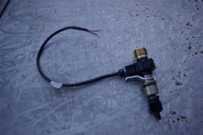
Update: Just found a Hall Effect Ford VSS from http://www.magsensors.com/

This unit should be a plug-n-play solution to generating the digital pulse that the PCM is looking for. It will plug directly into the D20 and has a mechanical passthrough for the speedometer cable. 3 wires hook it up. 12v - ground - and VSS signal. It comes in 2 - 4 - 8 - and 16 pulses per revolution. I've got a request in for a quote and hope to have some detailed info soon.

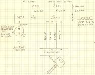
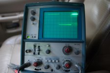
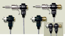
I verified the Explorer VSS signal has a digital pulse period of 7.5 ms and a duty cycle of 50% at 60 MPH. That coresponds exactly to 8000 pulses per mile. They offer the options shown in the picture below. The middle one would screw on to the back of the Bronco Speedometer with the spedometer cable screwed to the back of the sensor. I'm going with the upper right on which gives me the option of retaining the Bronco speedometer cable or ditching it for a electronic speedo. The signal can also be shared to drive an electroninc speedometer, navigation system, etc.

I still have to verify that the computer will not get confused by by low range on the D20. This could possibly present a problem since the transmission speeds would be higher than it's used to seeing in high range for a given vehicle speed. I already have a simple plan to correct that if it becomes an issue.

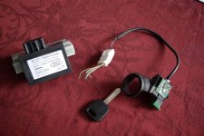
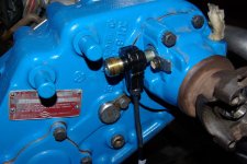
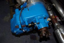
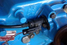
This will be a very clean and easy way to overcome the ABS generated VSS problem. Hope to have one in my grubby hands so I can verify that it will work in a few days. Just for reference that last picture is of a 1991 Explorer VSS and cable in the D20.

Update: Got the part ordered this morning. Should have it in a week or so. ($112)

Update: I also found the following today. http://www.dainst.com/info/circuits/oldVRSstuff I might give it a try today just for kicks. It would be a less expensive option but requuires building up a little circuit board.
 

Attachments

  • IMGP0006 (Large).JPG
    IMGP0006 (Large).JPG
    63.7 KB · Views: 78
  • vss.jpg
    vss.jpg
    55.2 KB · Views: 154
  • IMGP0001 (Large).JPG
    IMGP0001 (Large).JPG
    90.3 KB · Views: 177
Last edited:

MD

Jr. Member
Joined
Apr 1, 2004
Messages
76
The main reason is the TCM/ECM integration.

Same for me. I was able to get a complete 96 Explorer motor several years back, and I bought a 98+ 4R70W from BEcontrols to match. I really like the simplicity and durability of the stock electronics. I probably won't have as much stock emission stuff as Dave, but needing only one spare box for the engine/tranny/spark control is really great.

Michael
 

Broncobowsher

Total hack
Joined
Jun 4, 2002
Messages
35,059
The low range should be OK. Friend did a gear swap on his Explorer and played with speedo gears a while later. Nothing upset the computer.

The shifts are scheduled off the OSS on the transmission. Vehicle speed is more for emissions and speed limiter functions. Fords are known for going a bit conseritive (derating) when you reach 100 MPH. If you watch mustangs with stock computers at the strip you may notice them hit a wall at 100 MPH where they just don't want to go faster. I have had other Fords that at 100 MPH there was a noticable change in the performance. My chip burner asked if I wanted the engine to keep the derating at 100 MPH or if we should raise it, we bumped it to 255. The VSS also comes in handy for diagnostic work when looking at Freeze frame data, how fast were they going when it happened?
 
OP
OP
Dave

Dave

Contributor
Bronco Guru
Joined
Aug 25, 2006
Messages
2,245
The low range should be OK. Friend did a gear swap on his Explorer and played with speedo gears a while later. Nothing upset the computer.

The shifts are scheduled off the OSS on the transmission. Vehicle speed is more for emissions and speed limiter functions. Fords are known for going a bit conseritive (derating) when you reach 100 MPH. If you watch mustangs with stock computers at the strip you may notice them hit a wall at 100 MPH where they just don't want to go faster. I have had other Fords that at 100 MPH there was a noticable change in the performance. My chip burner asked if I wanted the engine to keep the derating at 100 MPH or if we should raise it, we bumped it to 255. The VSS also comes in handy for diagnostic work when looking at Freeze frame data, how fast were they going when it happened?


That sucks man! You mean my Bronco is going to be limited to 100MPH!;D

Thanks, Good info. It did seem to shift up and down just fine on the test stand without a VSS.
 

Broncobowsher

Total hack
Joined
Jun 4, 2002
Messages
35,059
If it is one that had the free tires after the little Firestone deal, I think part of the deal was a reprogrammed computer that lowered the top speed to 88(?) MPH. There were people who were not happy that they lost there top speed when they got there new, free tires. Aftermarket chip time!
 
OP
OP
Dave

Dave

Contributor
Bronco Guru
Joined
Aug 25, 2006
Messages
2,245
Test Completed - Running with codes

I got everything hooked up and chased down one bug that was caused by the fuel sending unit reference wire and the A/C demand wire being the same color code. It starts and runs impressivley well. It shifts up and down very smoothly. I hooked up the instrument cluster just for yucks. Not really all that many wires once you tie all of the grounds and power wires together. I don't intend on using it in the Bronco as I want to keep the stock gauges and It would be hard to find a way to mount it in the pannel and make it look right.

I've run the key on engine off and key on engine on tests with no faults detected. I did get a DTC for the Differential Pressure Feedback Sensor. Replaced it with one from the junk yard this morning and it cleared up that problem. The DTC troubleshooting proceedures really make it easy to track down problems. The live data grid is very handy for verifying all of the connections. You can look directly at signal inputs like the brake petal position switch, OD over ride, etc and watch them transition to verify that everything is connected correctly. That along with monitoring all of the engine parameters makes the OBD II very handy.

I'm back to work for 4 more days and hope to have my new VSS by the time I get home. More then... Dave...
 

Attachments

  • IMGP0001 (Large).JPG
    IMGP0001 (Large).JPG
    105.2 KB · Views: 90
  • IMGP0002 (Large).JPG
    IMGP0002 (Large).JPG
    111.6 KB · Views: 85
  • IMGP0004 (Large).JPG
    IMGP0004 (Large).JPG
    77.4 KB · Views: 74
  • IMGP0006 (Large).JPG
    IMGP0006 (Large).JPG
    62.6 KB · Views: 60
Last edited:

RnrdTheFox

Sr. Member
Joined
Dec 4, 2005
Messages
727
Loc.
Superior, CO
I've noticed that a lot of the ODBII code has options for low range transfer case strategies. Are going to try to utilize this option when you get everything going? I've always thought this would be a nice advantage of the ODBII code. Good driveability for street and trail...
 
OP
OP
Dave

Dave

Contributor
Bronco Guru
Joined
Aug 25, 2006
Messages
2,245
I've noticed that a lot of the ODBII code has options for low range transfer case strategies. Are going to try to utilize this option when you get everything going? I've always thought this would be a nice advantage of the ODBII code. Good driveability for street and trail...

From what I've learned so far on the 5.0L Explorer, all of the traction control and shifting of the transfere case is handled through the GEM which I'm not using. It would be a wiring nightmare. All you get with the scan tool is module not responding if you try to access it. No codes are generated. I can not find any communications or signal wires to convey any 4WD High/Low information to the PCM. The only modules that are on the SCP network are the PATS and the PMC (and temp control module is some modles) That is the only network that permits module to module communications. The GEM and all the others are the ISO 9141 which only communitions with a scan tool for setting parameters and diagnostics. There also no discrete wires to the PMC to signal that it in low range.
 
Last edited:

RnrdTheFox

Sr. Member
Joined
Dec 4, 2005
Messages
727
Loc.
Superior, CO
From what I've learned so far on the 5.0L Explorer, all of the traction control and shifting of the transfere case is handled through the GEM which I'm not using. It would be a wiring nightmare. All you get with the scan tool is module not responding if you try to access it. No codes are generated. I can not find any communications or signal wires to convey any 4WD High/Low information to the PCM.

Hmmm. That's a bummer.
 

oly24

New Member
Joined
Dec 2, 2007
Messages
23
Loc.
olympia
nice job

I am starting the same thing but with a 4/96 explorer I have a ? how do I tell if I have a pats system? The vehicle I got my parts from was at a wrecking yard but the steering colunm was gone But I got the engine, trans, and complete wiring from firewall out. also 90 percent of the wiring in the cab. Also how does the 96 get it speed signal if you know the answer this would be help full thanks

ps what kind of programm are you using to read the ecm
 
Last edited:
OP
OP
Dave

Dave

Contributor
Bronco Guru
Joined
Aug 25, 2006
Messages
2,245
I am starting the same thing but with a 4/96 explorer I have a ? how do I tell if I have a pats system? The vehicle I got my parts from was at a wrecking yard but the steering colunm was gone But I got the engine, trans, and complete wiring from firewall out. also 90 percent of the wiring in the cab. Also how does the 96 get it speed signal if you know the answer this would be help full thanks

ps what kind of programm are you using to read the ecm


I'm using the http://www.autoenginuity.com/ software and interface with the enhanced ford package.

I can't specifically address the 96 but since it was the first year for the 5.0 in the explorer you might look and see if there is a VSS on the rear of the transfer case. I know they went to a new version of the ABS in 98 which I believe was the first year that it output the VSS.

I think that the PATS was first introduced in 98 so that shouldn't be an issue.

I'm also using Alldata http://www.alldatadiy.com/?trackID=k75106 for reference. It seeme to be pretty complete and accurate for a shop manual. Takes a little time to get used to navigating around but once you do you can go directly to the information you need.

Keep us informed of you progress.
 
Last edited:

oly24

New Member
Joined
Dec 2, 2007
Messages
23
Loc.
olympia
Thanks for the info! I had the same thought has you, same controller for eng/trans. clean etc.... well see how it goes I don't have a degree in electrical engineering so this is a big project for me but very challenging,interesting and fun;D
 
OP
OP
Dave

Dave

Contributor
Bronco Guru
Joined
Aug 25, 2006
Messages
2,245
Thanks for the info! I had the same thought has you, same controller for eng/trans. clean etc.... well see how it goes I don't have a degree in electrical engineering so this is a big project for me but very challenging,interesting and fun;D

My tenacious nature has proven more valuable than my engineering background on these projects.;D Most of my engineering career was spent debugging and redesigning ill-concieved, poorly implemented, and undocumented manufacturing control systems. This stuff is actually quite nicely designed.
 

Wyldebill

Full Member
Joined
Feb 8, 2008
Messages
292
Loc.
Berthoud, Colorado
Hey Dave, I bought 74 project from a guy that was doing every thing wonderfully professional until he got to the wiring, and I think it overwhelmed him so much that he bailed on the whole project. If I could, I would like to tell you what I have, and more importantly, what I don't have and see if you can tell mee if I have enoiugth to follow the direction you are taking. I have a 2001 Explorer drive train, 5.0, 4r70w, and awd BW 4404 transfer. All have been mounted with the EFI 23 gal ank, with internal fuel pump and plumbed all the way to the fuel rails. The engine is complete just as it came out of the Explorer and it fits quite well due to a 2" body lift. I appear to have the entire wiring harness from the Explorer. I say appear, because it is stuffed in a large box and seems to have a wire and a connecter for just about every thing electrical on a Explorer. I haven't laid it out to see how complete it is because I don't know yet if it will be of any use to me as I do not have the actual computer from the Explorer. I also don't have, the ign. switch or key, nor do I have the vin: from the doner vehicle. I have tried to get the vin: but I have hit the wall every time. The guy that started this project, and appears that he knew what he was doing, is dead and doesn't want to talk. The thing that really confuses me is, in the pile of parts that was supposed to be "everything you need to finish the project," was an EECIV, ECM, complete with 60 pin plug with about an 18 inch cut off. This ECM has a DM code on it which as near as can tell comes from an 84 Bronco II. I can't figure out if he planned on trying to run a 2001 with an EEC IV, or if it was just a discard tht missed the trash can. Every thing that I consider seems to require modifications to the engine, or another computer just to run the trans. Soooo, my question to you is, can I try to do what you are doing, even though I do not have the ign. switch or the chip key, or the vin: to aquire them? And will the prorram that you using allow me to interface with the ECM with my windows driven laptop?
 
OP
OP
Dave

Dave

Contributor
Bronco Guru
Joined
Aug 25, 2006
Messages
2,245
Hey Dave, I bought 74 project from a guy that was doing every thing wonderfully professional until he got to the wiring, and I think it overwhelmed him so much that he bailed on the whole project. If I could, I would like to tell you what I have, and more importantly, what I don't have and see if you can tell mee if I have enoiugth to follow the direction you are taking. I have a 2001 Explorer drive train, 5.0, 4r70w, and awd BW 4404 transfer. All have been mounted with the EFI 23 gal ank, with internal fuel pump and plumbed all the way to the fuel rails. The engine is complete just as it came out of the Explorer and it fits quite well due to a 2" body lift. I appear to have the entire wiring harness from the Explorer. I say appear, because it is stuffed in a large box and seems to have a wire and a connecter for just about every thing electrical on a Explorer. I haven't laid it out to see how complete it is because I don't know yet if it will be of any use to me as I do not have the actual computer from the Explorer. I also don't have, the ign. switch or key, nor do I have the vin: from the doner vehicle. I have tried to get the vin: but I have hit the wall every time. The guy that started this project, and appears that he knew what he was doing, is dead and doesn't want to talk. The thing that really confuses me is, in the pile of parts that was supposed to be "everything you need to finish the project," was an EECIV, ECM, complete with 60 pin plug with about an 18 inch cut off. This ECM has a DM code on it which as near as can tell comes from an 84 Bronco II. I can't figure out if he planned on trying to run a 2001 with an EEC IV, or if it was just a discard tht missed the trash can. Every thing that I consider seems to require modifications to the engine, or another computer just to run the trans. Soooo, my question to you is, can I try to do what you are doing, even though I do not have the ign. switch or the chip key, or the vin: to aquire them? And will the prorram that you using allow me to interface with the ECM with my windows driven laptop?

It's is possible to program a ECM (PMC) to match the PATS but I'm not sure if my scan tool has that capability. Having a matching PATS and PMC makes it a lot easier. I'm going down to Denver tomorrow and was going to pull the PCM and PATS out of a 2000. The engine is gone but I wanted a spare to play with. I'll grab it and plug it in to my setup and program in a couple of keys. If it works, I'll help you get set up. The BW 4404 is the AWD case. No shifting functions or low range. Just a viscous coupling to the front. I'd stick a D20, Atlas, or 205 on it. You don't need the VIN or ignition switch. Just a couple of blank keys to reprogram it. If you want to run down to Boulder I can show what I'm doing and we can talk.

Dave...
 
OP
OP
Dave

Dave

Contributor
Bronco Guru
Joined
Aug 25, 2006
Messages
2,245
Network Schematic

This is the first of the electrical diagrams. I'm trying to be as complete and accurate as possible but can not be responsible for any errors of omissions. I'm not posting anything until it test and verify it first. Use this information at your own risk.%) Remember that all of these components run on smoke and mirrors. If you mess up you might let all the smoke out!

Here's what I'm running. The Connector on the left is the data link connector (DLC) (C291)* that the scan tool connects to. The CAN network (ISO 9141) is not being used and does not cause any issues. You simply get a component not found message for the devices that the scan tool looks for such as the ABS, Air bag controller, power seats, etc. It is a single wire (LB/WH) and does not allow communications between modules. Its only used for diagnostics and configuration by the scan tool. The SPC bus is a two twisted wire bus (TN/OG and PK/LB) that does allow two way communications between modules along with diagnostics, flash programming downloads and uploads, and parameter interrogation. There is also a Reprogramming Power Supply (flash) wire (VT) from the DLC to the PCM.

Those three wires connect to the engine/transmission harness through the block connector (C115M)*.

This stuff is really pretty straight forward and simple when you break it down into the individual functions.

* Connector numbers from the ALLDATA electrical diagrams.
 

Attachments

  • scan0040 (Large).jpg
    scan0040 (Large).jpg
    112.1 KB · Views: 131
Last edited:
OP
OP
Dave

Dave

Contributor
Bronco Guru
Joined
Aug 25, 2006
Messages
2,245
Passive Anti Theft System Schematic

Under Construction

The Passive Anti Theft System (PATS) module is located behind the passengers side airbag on the Explorer. Refere to the factory cautions and warnings when removing the airbag. Clip the connectors long enough to be able to splice them back together. The RF reader is located around the ignition tumbler. There is a 4 wire link to the PATS module. I'm using a blank key which has to be in pretty close approximation to the reader to get a good read. I've got a key taped into the reader for my tests. It does not need or use the key in ignition siganal for the PATS to function. I wired up the anti theft indicator with a 12 volt LED from Radio Shack. The only thing that makes it a 12 volt relay is that it has a built in current limiting resistor. (Important or the LED would look like a short to ground)

The LED flashes every 2 seconds with the ignition off. When the ignition is turned on it will turn off after 3 seconds if it reads the correct key. It will flash rapidly if it detects a theft (no or invalid key) and the PATS will tell the PCM to disable the engine. You can see the imobilized bit set in the PCM with the scan tool. It will also generate a theft detected diagnostic test code (DTC) that will be read until cleared with the scan tool. I think this will be a handy thing to have on the Bronco.

It is possible to reprogram the PCM to accept a different or new PATS. I'm not sure if my Scan Tool has that capability. It's best to have a PATS that matches (same vehicle) the PCM. If you have a key or set of keys for the donor you should be golden. If not you will have to program in new keys. My scan tool does this function as part of the enhanced Ford commands. I got a quote of about $75 a key at the parts store for blanks. Found them for $20 a piece at a lock smith shop. You need two keys to program it. There is a 10 minute security access delay after accessing the PATS and then you simply follow the instructions to clear the existing keys. Then you select the command to program new keys and wait another 10 minutes. When access is granted you put the first in the ignition and turn it on for 3 seconds then repeat for the second. It's now programmed. Im my case I held key near the reader and turned my temporary toggle switch on and off. Not an easy system to defeat.
 

Attachments

  • scan0041 (Large).jpg
    scan0041 (Large).jpg
    111.8 KB · Views: 77
  • IMGP0001 (Large).JPG
    IMGP0001 (Large).JPG
    127.9 KB · Views: 71
Last edited:
OP
OP
Dave

Dave

Contributor
Bronco Guru
Joined
Aug 25, 2006
Messages
2,245
Fuel System Schematic

Under construction

The fuel system consists of the in tank fuel pump, a fuel pressure regulator, fuel pump relay, inertia switch, fuel level sensor, fuel tank pressure sensor, a vapor recovery system purge solinoid valve and a vapor recovery system vent solinoid valve.

Sometime around 98-99 model year Ford switched from a return line system to a returnless system. The return line system has a pressure regulator on the fuel rail that is referenced to intake manifold pressure. Fuel pressure in the rail is maintained at around 38 psi. The PCM relies on the constant pressure to deliver a amount of fuel for a given injector control pulse width. The returnless system has a pressure regulator in the tank to provide about 65 psi in the fuel rail. The PCM has a fuel pressure sensor and a fuel temperature sensor in the fuel rail. It adjusts the actuall injector control pulse on the fly based on actuall fuel pressure and temperature at the time. I like it because it doesn't require a return line. That could be a real advantage in a two tank system. One pump in each tank with a tee. Each in tank regulator already has a check valve. Just switch to select which pump runs.

The PCM has an input for the fuel level which is the same signal that goes to the fuel gauge. It uses the fuel level along with a fuel tank pressure sensor to determine the volume of the vapor in the tank for the vapor recovery system. A solinoid valve is energized to draw vapors from the tank and vapor canister into the intake manifold. Another solinoid valve is used to vent the system.

pictures and schematics to come.
 
Last edited:
OP
OP
Dave

Dave

Contributor
Bronco Guru
Joined
Aug 25, 2006
Messages
2,245
Vehicle Speed Sensor Schematic

Danger Construction Zone

Still waiting for the hall effect sensor to come in from Calipornia. If it works like planned it will be a very simple diagram and instalation.

Shipping via UPS ground on Wednesday:cry:

Before you freak out, everything inside of the box is contained in the sensor. The 2 resistors are need to "pull up" the signal to the 6 to 7 volt level to mimic ABS output. The sensor provides a "open collector" output. Think of it like a switch that connects to ground when turned on. A lightbulb on the other end would have to be connected to power for the switch to turn it on. In this case the PCM, speedometer, and other devices require voltage to be supplied from the switch end. The two resistors divide the 12 to 14 volts power source (battery) in half to set the signal level to 6 to 7 volts. The open collector output shorts the bottom resistor to ground thus pulling the output signal to 0 volts.

Really quite simple. I installed the resisters in the connector on the VSS side. As far a wiring it into the system: Ground is connected to the cluster of balck wires in the harness. The power wire is connected to the group of red wires comming off the PCM relay which power all of the PCM components. The signal wire connects to pin 58 of the PCM. This is a grey/black wire in the harness that runs from the ABS to the PCM and also branches to the speedometer, curise control, radio, ans several other modules that use a speed signal. It would be very easy to retain the curise control if desired. The VSS signal will aslo drive other devices such as a navigation system.

Attached Thumbnails
 

Attachments

  • Picture 001 (Large).jpg
    Picture 001 (Large).jpg
    91 KB · Views: 149
  • IMGP0004 (Large).JPG
    IMGP0004 (Large).JPG
    87.4 KB · Views: 130
  • IMGP0005 (Large).JPG
    IMGP0005 (Large).JPG
    99.2 KB · Views: 158
  • IMGP0001 (Large).JPG
    IMGP0001 (Large).JPG
    78.6 KB · Views: 135
Last edited:
OP
OP
Dave

Dave

Contributor
Bronco Guru
Joined
Aug 25, 2006
Messages
2,245
Miscellaneous Systems Schematics

Construction Zone


The first schematic shows the ignition system connection. All that is required is fused circuit through the ignition switch that is hot in run and start which energizes the RD/LB wire comming out of the battery junction box powers the PCM power relay via PCM power diode. All of this circuitry is contained within the battery junction box and harness.

more to come:
 

Attachments

  • scan0042.jpg
    scan0042.jpg
    130.9 KB · Views: 75
Last edited:
Top