• Welcome to ClassicBroncos! - You are currently viewing the forums as a GUEST. To take advantage of all the site features, please take a moment to register. It's fast, simple and absolutely free. So please join our community today!
    If you have problems registering or can't log into your account, please contact Admin.

Windsor 5.0 Explorer Motor Wiring with Waste-Spark Coils

Alexander65

New Member
Joined
Aug 27, 2022
Messages
2
I started with a mustang 5.0 config then changed the ignition settings to custom with attached settings. At that point I believe if fired up and I noticed the sensor (oil, water temp & fuel pressure ) didn't seem accurate, don't overheat your engine! I spent copious time with multimeters and boiling water with the 5.0 sensors and recalibrating Holley graphs, then just decided to go with linear sensors. if you have the same setup pm me, I can send you my file, adjust injectors based on what you have, but the following should get you started. Unfortunately I didn't take notes and my memory yah.... that was the only major change to get it started - I think. the holly stock 5.0 iac isnt good (so no big if it hunts, just get it to start). once you get it started don't get to excited. I can send you a 2 or 3 things that made it run good.


https://yakely.com/classicbroncos/crank3.png

https://yakely.com/classicbroncos/crank2.png
How did you wire the coil drivers?
 

Alexander65

New Member
Joined
Aug 27, 2022
Messages
2
I started with a mustang 5.0 config then changed the ignition settings to custom with attached settings. At that point I believe if fired up and I noticed the sensor (oil, water temp & fuel pressure ) didn't seem accurate, don't overheat your engine! I spent copious time with multimeters and boiling water with the 5.0 sensors and recalibrating Holley graphs, then just decided to go with linear sensors. if you have the same setup pm me, I can send you my file, adjust injectors based on what you have, but the following should get you started. Unfortunately I didn't take notes and my memory yah.... that was the only major change to get it started - I think. the holly stock 5.0 iac isnt good (so no big if it hunts, just get it to start). once you get it started don't get to excited. I can send you a 2 or 3 things that made it run good.


https://yakely.com/classicbroncos/crank3.png

https://yakely.com/classicbroncos/crank2.png
Any tips on how to set up the iac mine won't idle down.
 

yakelys69

Sr. Member
Joined
Nov 20, 2006
Messages
737
I can't specifically look this weekend but Leech Motor Sports has excellent videos that I rely on for better understanding on each aspect. Look through this search on his YouTube channel. https://www.youtube.com/c/LeechMotorsports/search?query=fox holley

The tune file I gave you was what im using but I have a different cam and mix of parts. I also only run it up and down my local streets do to no lights & putting it on the sideline for the last year. It's' not a finished tune.
 
Last edited:

410Customs

New Member
Joined
Sep 21, 2022
Messages
12
Hello gentlemen!
My name is Jamie
I am building a custom Ford Ranger using s 2000 Explorer 302, Terminator X and the stock waste spark coil packs
This thread is awesome!!
I find myself in a similar situation
We have everything ready to go and the engine is cranking cranking cranking no fire.
It stumbles at times, before the crank sensor LED goes red
I do get some backfires

Setup is Holley term X with COP ignition harness running two 4 channel Holley coil drivers into the stock Explorer 5.0 coil packs
I have explorer 3 wire cam sensor
I am still using the 2 wire crank sensor (for now)
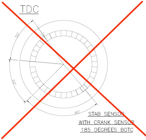
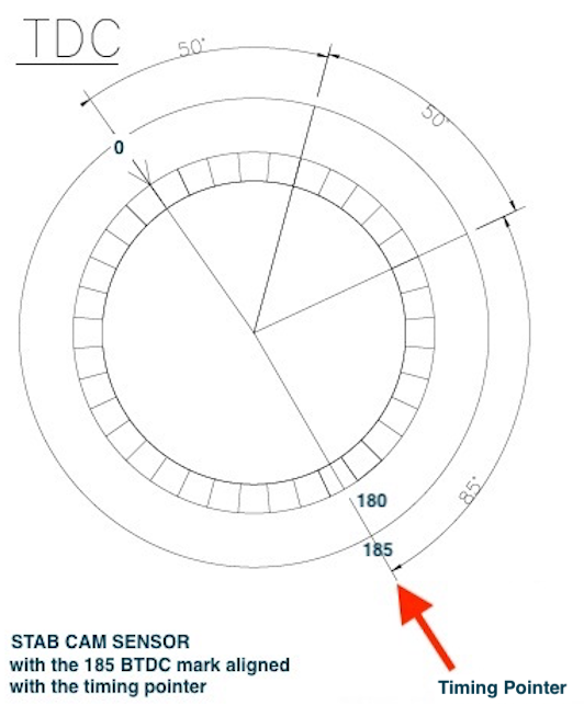
The cam sensor has been stabbed 185 out
I have fuel pressure at rail
Ford IAC is programmed for PWM wire has been assigned and it is working well
All systems are go, but still no fire
We tried 10 different global files we created yesterday, making progress. I have learned ALOT in a short amount of time (normal for me)
I have 30 years of building these trucks and MANY drivetrain conversions under my belt, I am a wiring guy

Which brings me here
I have one question to get us started, this is for @yakelys69
THANK YOU FOR POSTING ALL THIS INFO! It has been very helpful

In your coil pack wiring you only used the holley coil signal wires for coils 1, 3, 7 and 2?
Why?


Let me elaborate, what I mean is, not why did you do it this way? I understand the ford coil packs only have 4 coils/4 inputs.
I am just wondering if I am missing some info from Holley as to why you chose those wires?
Thinking of changing my setup to match yours


I have my coils combined for the waste spark,
meaning Ford Coil packs fire cyl 1 and 6 at the same time, so I combined the Holley coil signal wires for cyl 1 and 6
after the coil driver into the ford coil pack
I'm just curious if I need to change it to the way you have it setup!


Today I have a few more tricks to try, I am going to change where power for the cam sensor is coming from and I am going to make sure my crank sensor is well shielded. Then we will try again, hoping to hear this engine run today!

My ears are open to any ideas you guys may have!!
This 07 Ranger build can be found at Explorerforum, where I am a moderator.
 

410Customs

New Member
Joined
Sep 21, 2022
Messages
12
Any tips on how to set up the iac mine won't idle down.

Are you using the Explorer PMW style Ford 2 wire IAC?
I can help, I think! I set mine up yesterday
 

yakelys69

Sr. Member
Joined
Nov 20, 2006
Messages
737
In your coil pack wiring you only used the holley coil signal wires for coils 1, 3, 7 and 2?
Why?

Let me elaborate, what I mean is, not why did you do it this way? I understand the ford coil packs only have 4 coils/4 inputs.
I am just wondering if I am missing some info from Holley as to why you chose those wires?
Thinking of changing my setup to match yours


I have my coils combined for the waste spark,
meaning Ford Coil packs fire cyl 1 and 6 at the same time, so I combined the Holley coil signal wires for cyl 1 and 6
after the coil driver into the ford coil pack
I'm just curious if I need to change it to the way you have it setup!

The reason I did it this way was two fold.
  1. I don't know enough about the coil drivers to know if back charging one would possibly damage the driver or computer, I decided to avoid it.
  2. I decided to wire it closest to diagrams of original ford ECM wiring and how they did it,
    1. also on the ignition parameters -> custom -> output, DIS Waste Fire was an option with Dwell time of 1.5msec, I assumed this would work if I wired per stock ford.


My ears are open to any ideas you guys may have!!
This 07 Ranger build can be found at Explorerforum, where I am a moderator.

Mine had similar issues as you described, the 2 wire crank gave me more issues than the 2 wire cam. That being said adjusting the Ignition parameters I had the best success by changing the crank min sig volt to .30 and the filtering to level 4. I still had random issuess with inductive interference even with a shielded wire, to close to spark plug or some other wire and it was sporadic but try changing those and see if it helps.

This link is what lead me down that path and might be helpful to you.
Case 1: Ford Modular Setup in Custom Ignition Parameters
https://forums.holley.com/forum/hol...netic-amp-Hall-Effect-Crank-Cam-Sensor-Setup=
 
Last edited:

410Customs

New Member
Joined
Sep 21, 2022
Messages
12
all right! good enough
Thanks for the response!
Backfeed .....interesting point!
I combined the 8 coil driver signals, after the 4 channel drives, before going into the factory coil pack pigtails
Earlier today I moved my 3 wire cam sensor power feed to pin B20, no change
I tried voltaqes down from .35 down to .20
Have not set filter over level 4

cam synchro is set 185-190 out. Basically I had it set with the alignment tool like a stock explorer:
0 degrees TDC on compression, use alignment tool stab synchronizer.
For the Holley I then rotated the crankshaft 1 full turn so the 0 degree pointer was back, this is TDC on exhaust stroke.
I then went to 5 degrees ATDC, pulled the cam synchronizer, rotated the flag so the alignment tool fit once again, and re stabbed the synchro.
I understand this to be 185 degrees out


I will be doing some simple tests (air fuel spark timing, check wires and pins) before putting the truck through any more cranking

Basically I have all green lights
the cam and crank sensor go blue green blue green and the truck almost fires
Then the crank LED always goes red

I have read that thread/link thoroughly, I believe my crank sensor is too "noisy" or I need to make wiring changes to the coil drivers
Your setup at least had it running!!

thanks again I will report back!
 
Last edited:

yakelys69

Sr. Member
Joined
Nov 20, 2006
Messages
737
I think you coil drivers are probably fine, until that crank light stops going red it won't run.

Did you set you ignition parameters something like this?
crank2.png
 
Last edited:

yakelys69

Sr. Member
Joined
Nov 20, 2006
Messages
737
Im reading through your thread, very nice truck but I think you stabbed your cam at 185 ATDC but should be BTDC

Cam Sync setup ( Stab at 185° BTDC )

these are my notes: probably from multiple sources that I extrapolated what was relevant and likely wrote it in a way that I understood.
Cam Sync setup
Purpose is to identify when cylinder #1 is coming up.
Cam makes 1 rotation for every 2 rotation of the crank. Every other TDC cylinder #1 fires.

The cam sync signal trigger MUST occur:
* BEFORE cylinder #1 is at TDC on the COMPRESSION STROKE
* It also must occur at least 50 degrees BEFORE the “missing tooth” read by the crank position sensor.

“Ignition Reference Angle” = Taken from Crank Sensor Setup in software
“A” = Angle Between Crank Pulses (crank degrees between triggers on the crank sensor)
  • “A” for a 8 cylinder = 90°
"Ignition Reference Angle" + “A” + (“A” / 2) = Cam sync location (degrees BTDC #1)
50 + 90 + 45 = 185
 
Last edited:

yakelys69

Sr. Member
Joined
Nov 20, 2006
Messages
737
The rest of my notes on this. no need to print out degree wheel each tooth is 10 degrees. Put on TDC mark teeth as needed. 36-1 trigger has 35 teeth missing one so 36 x 10 = 360

Crank Sensor ( 50° BTDC = Ignition Reference Angle )
Missing tooth is used to identify the Crank Position,
Other teeth are used for RPM and timing

Put Engine at TDC (engines rotates clockwise)
* This will be compression stroke of cylinder 1
* Can tell by placing finger over plug hole
* Also it will be after the intake valve opens, if you can see it

Crank Trigger is 36-1 tooth
* Every tooth is 10 degrees
* With engine at TDC , The crank sensor is on the 5th tooth
* So the ignition offset is 50 degrees

Note: the Ignition Reference Angle set in the software is is typically set to a value that is 10° more than the highest timing you will run. Do NOT set it higher than 75°.
 
Last edited:

410Customs

New Member
Joined
Sep 21, 2022
Messages
12
YOU ARE AWESOME!!

Yes our ignition parameters are similar except I have the coil dwell time set to 3.0 Msec which is good for the Ford coil pack

I will check my crank to cam timing and re set the synchro, I bet that is it. The ECU is telling us what is wrong 6th led goes to red

it is a problem with the crank signal OR with the cam crank timing!!
SO I BET YOU ARE RIGHT my cam synchro is not stabbed correctly

We have a similar setup on the forum, dude from Canada except his 2 door explorer is a supercharged 347, he setup a similar kit to mine, and is having similar issues......

I will work on this today! I have my cam synchro at 10 ATDC on exhaust stroke
 
Last edited:

EPB72

Contributor
Sr. Member
Joined
Jul 13, 2019
Messages
810
Loc.
Pleasant Hill, CA
410 ,,so I'm just going to throw this out there, is there a possibility the crank sensor wires are reversed, this will give you an Inverted signal waveform that the processor will probably not like,,...I see in Yakleys setting picture that it appears senor type is programable falling or rising??
 

410Customs

New Member
Joined
Sep 21, 2022
Messages
12
410 ,,so I'm just going to throw this out there, is there a possibility the crank sensor wires are reversed, this will give you an Inverted signal waveform that the processor will probably not like,,...I see in Yakleys setting picture that it appears senor type is programable falling or rising??

correct! I have same cam synchro, 3 wire, hall effect type.
The application is 96-98 explorer 5.0
The 99-01 5.0 explorers use a 2 wire cam sensor with 01 being the last year of the SBF 302
I ordered a brand new motorcraft 3 wire for this truck

I have checked my wiring vs the posted diagram picture yes.
ground on top, middle is signal, bottom is 12V+ clean power now from pin B20 at PCM
The stock 5.0 cam sensor wiring (for the explorer 3 wire is sensor) matches the picture yakelys69 posted

I also read about some LS engines with the Holley where they had to swap the pins on the cam sensor? Not exactly sure what that is all about
I am used to just setting the cam synchro with alignment tool and cyl 1 at TDC compression, one and done

I have it set to falling
as I understand it, the half moon leaves the window as the cam synch flag passes by?
Which is why we set it to falling


Lucky for me I have converted several Rangers to 5.0 before this using the stock explorer pcm
This is the first Holley 5.0
and this is the first Can Bus Ranger, 2007, no longer obd2
There have been some challenges.

The consensus is I have the cam sensor set not correctly
It needs to be at 185 degrees BTDC
that will happen very soon!!

crosses fingers
 

410Customs

New Member
Joined
Sep 21, 2022
Messages
12
Here's the deal
setting the cam sensor 185 degrees before tdc cyl 1 on compression stroke is NOT SIMILAR to having your distributor (or cam sensor) 180 degrees out of time!!!
That is where I got confused

when setting up Holley terminator X for a Ford with cam and crank sensors information on the web says to "set your cam sensor 185 out"
To me that is setting the dist on tdc exhaust stroke as we discussed, and 5 degrees away from that. (0 mark on balancer, but tdc on exhaust stroke)

"hey doofus your're 180 out of time" right? we have all seen/done it

The actual instructions from Holley are to Set the cam sensor 185 degrees before top dead center


LIKE THE PICTURE posted long ago right here!!
with the crank rotated 185 degrees before TDC occurs...........
Two totally different things!!!
Now I have clear direction and will report back

THANKS TO THIS THREAD!!!!!
Having the correct information is priceless
talk about a brain fart
 
Last edited:

yakelys69

Sr. Member
Joined
Nov 20, 2006
Messages
737
The engine goes clockwise, Your image shows 175 BTDC or 185 ATDC. Think of it like this from TDC if you were to rotate the engine backwards 185 degrees thats the spot that should be marked. So that mark should pass your timing pointer 185 degrees before TDC does when going clockwise. Might be good to remove that picture so others don't get confused.


wrong.jpg
 
Last edited:

yakelys69

Sr. Member
Joined
Nov 20, 2006
Messages
737
I suppose its how you interpret things. Try it like this. It's about where the engine rotation is, not where the sensor is. The location of the sensor is how the 185 is derived. "Ignition Reference Angle"

correct2.png
 
Last edited:

410Customs

New Member
Joined
Sep 21, 2022
Messages
12
410 ,,so I'm just going to throw this out there, is there a possibility the crank sensor wires are reversed, this will give you an Inverted signal waveform that the processor will probably not like,,...I see in Yakleys setting picture that it appears senor type is programable falling or rising??
@EPB72
Can you elaborate on this?
I read a little about this, but it was for LS engines (having a red crank LED, same as me)
my cam sensor is setup as digital falling
my wires match the picture

yesterday I re timed my cam sensor, she is now stabbed at 185 degrees before top dead center.
Same thing, cranks and cranks, green blue green blue then finally red 6th led

So today I will:
Test for spark
test fuel injector power wire and PCM pulse. I have been told the Holley will not fire the injectors if the cam/crank timing is out (FUN!)
I am considering changing my coil driver wiring to match @yakelys69 col driver wiring (remove 4 of the signal wires)

After that I am stumped
I do have a hall effect style crank sensor in the mail, but it is my understanding it should run with the setup I have
Riding the roller coaster
 
Last edited:

410Customs

New Member
Joined
Sep 21, 2022
Messages
12
okay found another issue, hopefully this is it!
Once again I am a doofus

Looking over my coil pack wiring diagram (I created, this is how my project is wired)
I have pins for cyl 6 and 7 reversed at pcm!!!!!!!!

FIXING THIS NOW

bad picture, this is from when I first laid my wiringout in cad
PIN 24 is for cyl 7
PIN 17 is for cyl 6

BACKWARDS from day one

image_2bb-jpg.430423


With waste spark I can only imagine what kind of MISFIRES this would create
Two trucks are wired from this diagram, both trucks having SAME ISSUE
 
Top