• Welcome to ClassicBroncos! - You are currently viewing the forums as a GUEST. To take advantage of all the site features, please take a moment to register. It's fast, simple and absolutely free. So please join our community today!
    If you have problems registering or can't log into your account, please contact Admin.

Dan Wheeler's Radius Arm Build Thread

DanWheeler

Bronco Guru
Joined
Nov 8, 2005
Messages
2,549
Loc.
Kirkland, WA
I'm in the process of building extended radius arms using a set of stock arms, some 2" x 1/4" wall DOM, 3" Ballistic joints and Ballistic frame link mounts.

The motivation behind these arms was to save around $400 over Cage or Duff arms. I've got about $400 into them so far and that should be pretty much it. The joints and the DOM are pretty expensive but I'm sure there are cheaper ways to do the same thing. I went with the 3" ballistic joints becuse they take a 3/4" bolt. Johnny Joints take a 9/16" bolt. I figured if 2 bolts are going to be holding my entire front-end in place then I would feel better if they were bigger than 9/16ths.
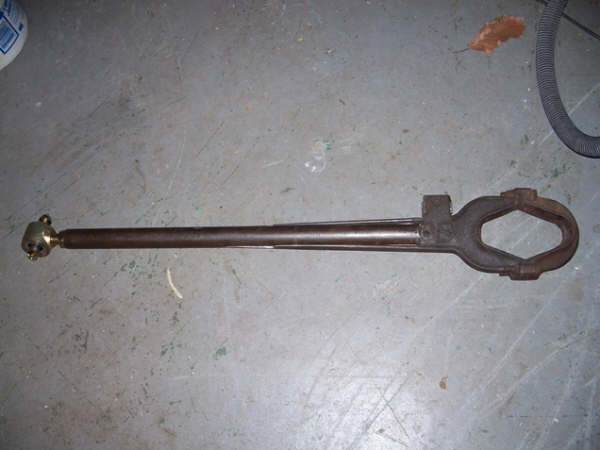
Stock Arms:
542710643_gh4kR-M.jpg


The 3" Ballistic joints:
542711466_9CC3w-M.jpg


Cut at 8" from inside of edge with a chop saw:
551543024_uT8Ae-M.jpg


Radius arms cut along inner edges:
551543183_YwGFv-M.jpg


I started out by cutting off the shock mounts with my cut-off wheel. I then started cutting along the inner edge of the arms with the cut-off wheel. I finished both sides of one arm with the cut-off wheel before thinking to try my chop saw. The chop saw cut along the inner edge cleanly and quickly.

551543166_7n8FQ-M.jpg


a quick perpendicular cut with the cut-off wheel and the radius arms are hollow and ready for tubing:

551543616_Zpgx4-M.jpg


(i know the bends are pointing the wrong way in these pics)
551543468_9EHJN-M.jpg


Many thanks to a local Bronco owner for making these bends for me. Trying to bend quarter inch wall DOM proved too much for the bender as it came from the factory but the professional welder that he was he was able to weld it back together and get a perfectly matching 8 degree bend in both arms.

Next I will notch the DOM so it can sit flush against the inside edge of where the C-bushing goes.

551543469_io7eF-M.jpg


leftovers:
551543652_7TuaD-M.jpg


Once the centers are hollowed out it's not too difficult to pound out the remaining ears to make room for 2" DOM. The only thing I'm concerned about is making sure things are straight so I dont end up with more caster on one side than the other.

I haven't decided how long I'm going to make the arms. I'd like the option of going with equal length radius arms in the rear if I ever go that route.

One thing I wish I would have done is ordered custom frame brackets from Ballistic. I wanted them to make a dual-mount frame bracket so I could connect a radius arm pointing forward and one pointing backwards. They only wanted $60 for left/right brackets.

Next steps are to grind down the inside of the ears smooth and make sure the angles for the ears are identical between the two radius arms then start welding.

hopefully more to come Tuesday or Wednesday night.
 
Last edited:

bigjhoov

nobody
Joined
Apr 10, 2005
Messages
3,581
You should have slit the tubing and slid the radius arm in I think. Might have made things a little easier an stronger. I'll still watch to see how it turns out. Maybe you have another trick up your sleeve. Good luck with it.

radiusarm2.jpg


radiusarm1.jpg


RadiusArm.jpg
 
OP
OP
DanWheeler

DanWheeler

Bronco Guru
Joined
Nov 8, 2005
Messages
2,549
Loc.
Kirkland, WA
You should have slit the tubing and slid the radius arm in I think. Might have made things a little easier an stronger. I'll still watch to see how it turns out. Maybe you have another trick up your sleeve. Good luck with it.

No tricks up my sleeve just a different approach. Either way will be plenty strong enough. I didn't want to compromise the strength of the DOM by slotting it not that it would probably really matter at 1/4" wall thickness but that was my train of thought. I also didn't trust myself to cut 8 straight, perfectly spaced, parallel lines with a cut-off wheel through 1/4" DOM. Cutting the insides of the radius arms out is about half the amount of cutting necessary compared to slotting the DOM. If I had a bandsaw and some sort of jig it might be a different story. Hollowing out the radius arms with a chop-saw was super easy and allows me to use 2" tubing with a longer contact surface because I am able to stretch out the remaining ears to a 2" gap.

I will slot the ends of the DOM a little less than 1" and round out the end of the DOM so it can butt up against the edge of the C and run a weld there. That will give it strength laterally.
 

SC74

Contributor
Bronco Guru
Joined
May 24, 2004
Messages
3,413
I also slotted the DOM, but like you said it is a PITA to cut 1/4 wall tubing. We made a simple jig to mark our cuts. Good work so far.
 

u10072

Bronco Guru
Joined
May 18, 2007
Messages
2,249
I totally agree-- the DOM should have been slotted not the radius arm. Lars is a mechanical engineer and a pretty smart guy. Just something that anyone might think about-- just because its easier doesn't mean you should. Personally just sitting here thinking about it I am not sure of the safety of that arm. Sorry to piss on the parade
 
OP
OP
DanWheeler

DanWheeler

Bronco Guru
Joined
Nov 8, 2005
Messages
2,549
Loc.
Kirkland, WA
I totally agree-- the DOM should have been slotted not the radius arm. Lars is a mechanical engineer and a pretty smart guy. Just something that anyone might think about-- just because its easier doesn't mean you should. Personally just sitting here thinking about it I am not sure of the safety of that arm. Sorry to piss on the parade

Give it some more thought before you judge it based on it being different than the "standard". Just because someone "smart" did something one way doesn't mean the other way is wrong. Did you think about what would have to happen first before this design would fail? If you have an actual reason why you think they will fail (and/or more likely to fail than the alternative design) then I would be interested to hear that.
 

kbldawg

Bronco Guru
Joined
Jun 26, 2007
Messages
1,492
Loc.
Marshall, AR
I'll betcha your design is just as strong as the Lars version.

It comes down to welding. You've got just as much weld contact area as the Lars method. Provided your welding skills are good, my inclination is that those arms will last a very long time.

Nice job!
 

Dusty

Bronco Guru
Joined
Jun 28, 2001
Messages
2,965
I think both versions are fine. The strength is in the .25 wall DOM, not so much whatever remains of the original arm. One might seem a bit easier to do than the other, but I think either way, done carefully with good welds, should be fine. I'll be curious to see how those bends hold up to some serious pounding.

Dusty

EDIT: LOL...kbdawg beat me to it! He types faster...
 
OP
OP
DanWheeler

DanWheeler

Bronco Guru
Joined
Nov 8, 2005
Messages
2,549
Loc.
Kirkland, WA
let me give a little more detail to back up my claims.

The stock radius arms are essentially an I-beam. An I-beam consists of 2 flanges and a web. (the 2 flanges are on top and the web ties the flanges together) I'm sure we all know how an I-beam gets it strength to resist bending in both directions so I wont get into that.

For this explanation let's call the length of the radius arm the Z axis, the axle tube the X axis and the remaining axis is the Y with the center of all 3 axes converging somewhere below the stock shock mounts on the "web".

So what I've done with my design is removed the web of the I-beam and left just the 2 flanges. I've replaced the web with a large tube which has similar properties as an I-beam but with better resistance to torsion. For the purposes of this application, the resistance to bending of the tube compared to an I-beam is not a realistic factor to be concerned with.

Now, i'm bringing my DOM tube all the way up to the C and we certainly dont need to worry about bending the DOM especially if I haven't compromised its strength by cutting a huge slot down the middle :D

So we are left with the two "flanges" from the orginal I-beam resisting any bending/rotation on the Y axis. Those are the same two flanges present on the stock radius arm minus the web that was there previously. It's worth noting that the "web" of the I-beam provides almost no strength to resist bending around the Y-axis. As I stated, I've replaced the web with a big-ass tube that WILL resist bending around the Y-axis. The 2 flanges welded to the top and bottom of the DOM provide every bit as much of resistance to bending around the Y as they do in the Lars design. In addition, the tube is providing even more resistance to bending around the Y-axis.

On the X-axis, we are concerned about the C rotating or bending up or down in relation to the DOM tube. (affecting caster essentially) For this to happen the top flange would have to stretch and the bottom flange would have to compress or vice versa. I dont see 1/4" steel stretching OR compressing under the forces put on this radius arm. If that were a concern, then the radius arms would not be sufficient in their stock form.

so if you ask me, this design is stronger than stock and stronger than Lars' design because you are eliminating 3-4" of potentially weak I-beam area between the C and the DOM and replacing it with 2" x 1/4" wall DOM.

Just my uneducated opinion though.
 

needabronco

Bronco Guru
Joined
Jul 2, 2004
Messages
6,411
Loc.
Prescott/Farmington
Dan, were not dogging your work here, just offering a little bit of insight. The reason Lars' and everyone else leaves the webbing in the arms is for latteral strength. By slotting the DOM and fitting it both the radius arm and the DOM togheter actually adds about twice as much weld area, and IMO strenghens the entire arm. In effect the DOM has a cross piece making it even stronger. This adds strength to the arms so that they are stronger than the stock I beam design and can hold more sideload without failure.

This is how I build my arms, if fact I use Lars's cad drawing and use a jig he designed to minimize warping of the radius arms (yes they take on that much heat).

Can I ask why you bent your DOM so close to the radius arm? This is a serious question, as most of us put the bend on the other end, I'm just wondering what your thought process was. Again, I'm actually commending you for thinking 'outside the box', and I'm curious...
 
OP
OP
DanWheeler

DanWheeler

Bronco Guru
Joined
Nov 8, 2005
Messages
2,549
Loc.
Kirkland, WA
Can I ask why you bent your DOM so close to the radius arm? This is a serious question, as most of us put the bend on the other end, I'm just wondering what your thought process was. Again, I'm actually commending you for thinking 'outside the box', and I'm curious...

Thats funny I had wondered the same thing about putting the bend closer to the frame mount. I actually don't understand the benefit of putting the bend by the frame mount.

I might be missing something here but the closer you put the bend to the frame mount the less effective it is at reducing the bind on the C-bushing caused by moving the mount point back on the frame which essentially is like pulling the radius arm away from the vehicle 2-3 inches or a few degrees.

imagine if the 10 degree bend was 2" from the heim or flex joint. The amount of correction (and when I say correction, I mean the location that the C bushing sees as a straight line towards the frame) would be so small that it would be just like having a straight bar which does nothing to reduce bind on the C bushings.

now imagine if the bend was 2" from the C bushing. In this case it WOULD correct the angle of the radius arm but would do little to help with tire clearance on the radius arm.

If you put that bend right in the MIDDLE of your radius arms you are creating the largest possible isosceles triangle. (from the point of the bend with equal lengths to each end of the tube and equal angles at the ends of the tube).

now this is where I'm confusing myself and may have been better off putting the bend right in the middle. I put the bend exactly where the outside of my 35" tire would hit the radius arm. I figured this would give me the most clearance.

Now that I think about it, putting the bend in the middle of the radius arm would have given me the most tire clearance while still correcting for the C-bushing angle.

as you move the bend up or down the radius arm towards the frame mount or towards the axle you lose tire clearance.

sound right?
 

trailpsycho

Bronco Guru
Joined
Dec 11, 2003
Messages
4,856
There is nothing weakened in either part of the Lar's Barz, b/c the gap in the tube is being filled by the material of the stock arm and then the tube is welded to both the web AND the "ibeam" portion of the stock arm.

Now, dont get me wrong. I think your design will be fine once its welded properly. That being the key point. The "cool" thing about Lar's design was that once the bend or slot in the tube was established relative to each other (not sure which they did first), but once it was set, the bend for clearance would be set relative to the head.

In your design, not only do you have to get the tube perfectly alligned down the cut out area of the stock arm, BUT you also have to now make sure the bend in the tube is at the appropriate angle to the head of the arm (a potentially big issue that Lar's design takes into account). However, as long as you factor in those issues and get some nice, deep welds in there, you should be good.

Cant wait to see more progress. Best of luck. Dont take anybody's comments personal, they are simply trying to be helpful.
 
OP
OP
DanWheeler

DanWheeler

Bronco Guru
Joined
Nov 8, 2005
Messages
2,549
Loc.
Kirkland, WA
also, the further up the arm towards the frame you put your bend the more you have to rotate you frame mount or use up rotation degrees on your joint.
 
OP
OP
DanWheeler

DanWheeler

Bronco Guru
Joined
Nov 8, 2005
Messages
2,549
Loc.
Kirkland, WA
There is nothing weakened in either part of the Lar's Barz, b/c the gap in the tube is being filled by the material of the stock arm and then the tube is welded to both the web AND the "ibeam" portion of the stock arm.

you're right, i forgot that the web part of the ibeam is in addition to the slotted DOM however I still think if you're going to use 1/4" wall DOM then you should take it all the way to the C.

If you dont go all the way to the C with the DOM then you are left with a section of stock strength radius arm. I'd be interested to see how 1/4" DOM would hold up against a stock radius arm in a tubing bender (if you could fit a stock radius arm in a tubing bender)
 

needabronco

Bronco Guru
Joined
Jul 2, 2004
Messages
6,411
Loc.
Prescott/Farmington
The way I understand radius arms is that the 'C' bushings have very little to due with flex. The joint on the end of the arm does all of the flexing. The 'C' bushing only locates and maybe isolates the axle. When you flex your suspension the joint at the frame mount 'flexes' the most, while the 'C' doesn't move, at least hopefully doesn't...

According to Lars' and by studying others long arms, and from building them myself, if you bend the arm approximately where the stock radius arm mounts to the frame you in effect do not loose any steering geometry. I can turn my tires just as far as I did with stock radius arms. If I could turn them any further I'd probably scare myself... If you utilize a bend at that location and use a longer arm you get all of the benefits of a long arm including more flexibility due to the joint on the end of the arm, and you don't see the loss of turning radius. I don't know what the difference would be having your bend at the front or in the middle of the arm. But think of this if you take a piece of study wire with a bend it the middle if you push the ends together the wire will bend easier than if the bend was at the very end of one end, right?
 
OP
OP
DanWheeler

DanWheeler

Bronco Guru
Joined
Nov 8, 2005
Messages
2,549
Loc.
Kirkland, WA
According to Lars' and by studying others long arms, and from building them myself, if you bend the arm approximately where the stock radius arm mounts to the frame you in effect do not loose any steering geometry.

I get it now. that makes perfect sense - bring the tube straight up to the frame where it would have been a straight shot for the stock arm then bend it straight back the rest of the way to the new frame mount which is further back.

Cage and Duff both have the bend down by the C bushing. Now I'm not sure if that was by design or because they dont want to bend 1/4" wall DOM.

with regards to your study wire example, yes the bend in the middle would be more likely to bend however if you put a bend at the end wouldn't the long section be more likely to bend? Either way, this DOM aint bending :D (we broke a bender die just trying to get 10 degrees)

also, regarding the c-bushings and flex - the C-bushings are absolutely responsible for a significant amount of flex. Imagine if one wheel was stuffed in the wheel well and the other was dropped down in a hole. There would be a difference in rotation of your radius arms which is handled by the C-bushings (albeit, not very easily and not very well) Either the c-bushings flex or the axle housing twists. (which we know its not supposed to unless you have the wristed axle housing)
 
OP
OP
DanWheeler

DanWheeler

Bronco Guru
Joined
Nov 8, 2005
Messages
2,549
Loc.
Kirkland, WA
i guess if it turns out the bend is better off near the frame then i'll just turn the bars around. Haven't welded them yet. Anyone else have thoughts on that?
 
Top