• Welcome to ClassicBroncos! - You are currently viewing the forums as a GUEST. To take advantage of all the site features, please take a moment to register. It's fast, simple and absolutely free. So please join our community today!
    If you have problems registering or can't log into your account, please contact Admin.

'70 LUBR Build

5_oh_bronco

Jr. Member
Joined
Nov 10, 2014
Messages
64
Loc.
Grand Junction
So I've been working on building a 1970 uncut Bronco.

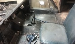
This is my first build, so it is moving along slowly, but moving. I started with a pretty clean, mostly complete, running bronco last July. While most of it was there, the interior was in pretty rough shape. It appeared to have been rolled, and repaired. Repairs included fixing dents along both upper outside corners of the hard top, straightening (sort of) the core support, replacing both fenders, and brazing a few broken spot welds along the inner fenders. Rear quarters are in great shape, as is the bed, firewall, transmission tunnel, and dash. Rust was found in the usual areas: bottom of the a-pillars, one rocker, bottom of the tailgate, the double layered portion of the inner fender immediately ahead of the firewall, and of course, the floor pans.

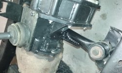
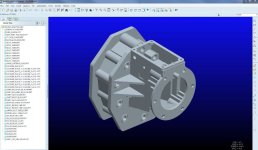
The plan: the original 302 is being replaced with a fuel injected, computer controlled 5.0 out of a '95 mustang. The original 3-on-the-tree tranny is being swapped for the WCT5 5-speed, also from the mustang. This is being mated to the original dana 20 with an adapter of my own design and fabrication. Maximum lift will be about 1-1/2 to 2 inches, depending on how much the extra weight of the 5.0 causes 2 inch lift springs to sag. Tires will be a 30 x 9.5 riding on the original rims with original hub caps. Drum brakes will be swapped for discs at all four corners, powered by an astro-hydraboost conversion. Power steering will replace the original unassisted unit. Ideally, this thing will look basically original until you pop the hood. Under the hood it should look like a stock '95 mustang.

Current status:
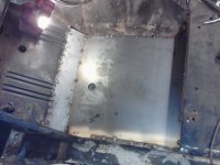
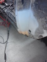
Body: all rust has been repaired, and brazed spots have been cleaned and re-welded. New floor pans were fabricated and welded in place. The poorly straightened sections of the core support have been less poorly straightened.

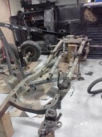
Chassis: The chassis has been stripped bare, blasted, and painted.

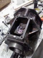
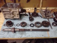
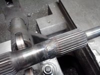
Drive train: All drive train components have been removed. The original 302 has been removed and is sitting on a stand, 5.0 is ready to be installed. The WCT5 tranny has been torn down and inspected. The main shaft still needs to be shortened before it will be ready to be mated to the adapter. The adapter has been designed, and will be fabricated shortly. Both axles have been torn down. Housing have been blasted and painted. I haven't touched the rear axle shafts yet, but will be doing so soon. I'm about 75% done with the front disc conversion. My conversion includes spindles, hubs, caliper brackets, and calipers from a '79 Ford F-150. I've modified the spindles to fit the Dana 30 knuckles. I've also modified the Dana 30 king pins by adding a grease zirk.

It's a long road ahead, but I'll update this post with pictures and progress reports as I go. As soon as I organize the pictures I already have, I'll post a few of them.

I started a thread a few months back to ask some questions pertaining to the engine swap I'm doing. There are a few pictures there. The following link should take you to that thread:

http://classicbroncos.com/forums/showthread.php?t=248267

Of course, any comments are welcome.

Hope you enjoy the show!
 
OP
OP
5

5_oh_bronco

Jr. Member
Joined
Nov 10, 2014
Messages
64
Loc.
Grand Junction
As promised, here are a few pictures:
 

Attachments

  • Original1.jpg
    Original1.jpg
    108.6 KB · Views: 300
  • drivers inner fender doubler replaced with single 8th inch piece.jpg
    drivers inner fender doubler replaced with single 8th inch piece.jpg
    97 KB · Views: 253
  • new_pass_floor.jpg
    new_pass_floor.jpg
    257.9 KB · Views: 275
  • pass_floor_cleaned.jpg
    pass_floor_cleaned.jpg
    282.9 KB · Views: 267
  • new_drivers_floor.jpg
    new_drivers_floor.jpg
    213.2 KB · Views: 266
  • drivers_floor.jpg
    drivers_floor.jpg
    103.1 KB · Views: 252
  • top_removed.jpg
    top_removed.jpg
    253.2 KB · Views: 240
  • disassembly_begins.jpg
    disassembly_begins.jpg
    101.5 KB · Views: 253
OP
OP
5

5_oh_bronco

Jr. Member
Joined
Nov 10, 2014
Messages
64
Loc.
Grand Junction
And a few more pics:
 

Attachments

  • ProE-TrannyAdapter_scrn_sht1.jpg
    ProE-TrannyAdapter_scrn_sht1.jpg
    82.3 KB · Views: 210
  • T5_disassembled.jpg
    T5_disassembled.jpg
    273 KB · Views: 227
  • painted_frame.jpg
    painted_frame.jpg
    261.9 KB · Views: 243
  • blasted_frame.jpg
    blasted_frame.jpg
    162.6 KB · Views: 214
  • frame_before_blast1.jpg
    frame_before_blast1.jpg
    252.5 KB · Views: 213
  • frame_before_blast2.jpg
    frame_before_blast2.jpg
    233.5 KB · Views: 221
  • passenger_a-pillar.jpg
    passenger_a-pillar.jpg
    234.1 KB · Views: 205
  • drivers_a-pillar.jpg
    drivers_a-pillar.jpg
    106.9 KB · Views: 224

bsquared

Contributor
Sr. Member
Joined
Dec 4, 2010
Messages
961
Wow...great looking build, man! Keep the pics coming, sounds like it's going to be a great ride when you done. Good luck! B2
 

jimmyk

Contributor
Full Member
Joined
Nov 12, 2013
Messages
238
I have a friend who built an adapter for the T5, so I know it CAN be done, just takes patience and know how. I went the zf5 route, just got my adapter in the mail and hope to install it soon.
 
OP
OP
5

5_oh_bronco

Jr. Member
Joined
Nov 10, 2014
Messages
64
Loc.
Grand Junction
Thanks for the encouraging words, everybody.

Progress never seems to happen as quickly as I would like, though perhaps that is always the case no matter what I'm working on!

Since the last update, I've been working on the rear axle shafts a bit. I've turned the outer flange down in diameter to be able to fit a rotor over it. My rear disc set-up will include brackets that I fabricate, and cadi-calipers with the built in parking brake.

As for my T5 adapter...
I have a friend who built an adapter for the T5, so I know it CAN be done, just takes patience and know how
- jimmyk
The patience part I've got, it's just the "know how" portion that worries me! Fabrication should begin soon. I designed it to make fabrication as straight-forward as possible. If you take a close look at the picture in the post above, you can see that it is largely made up of flat plates that will be welded together. The plates are all being cut on a laser, many with tabs and slots to make the adapter fit together like a puzzle. Once assembled, it will be welded. Finally, there will be some finish machining to do to ensure precise alignment for all internals. It'll be interesting. I'll post pictures.

BTW... That "strange vehicle" sitting next to the '70 in the driveway belongs to a friend. I drive something far more sacrilegious: a '73 K5 blazer! (due up for a frame-off after the bronco is complete!)
 
OP
OP
5

5_oh_bronco

Jr. Member
Joined
Nov 10, 2014
Messages
64
Loc.
Grand Junction
Below are a few more pictures. The first picture is of one of the 9-inch axle shafts mounted in the lathe, being checked for total run out. When I first drove the bronco back to my house, I knew something wasn't right, as it developed quite a lurch above about 35 mph. This axle shaft had a bend that resulted in about .031" of total run out. A little work on a shop press brought it down to less that .005", which was the best I could do. If it still causes problems, I suppose there are probably a few suppliers out there who would happily sell me a new one.

The other pictures are of my modified '79 F150 Dana 44 spindles and caliper brackets. Rumor has it that a '73-'76 Chevy Dana 44 spindle and bracket will bolt straight to the '66-'70 Bronco Dana 30 knuckle, and that the F150 hub will fit on the Chevy spindle. That is confusing, hard to find, and it wouldn't taste right to put Chevy parts on a classy '70 Ford Bronco. That would be like eating a perfectly seared Fillet Mignon with a plastic fork. I guess it would work.

My approach was to stay with genuine Ford parts by modifying the F150 spindle and caliper bracket. The shoulder on the spindle that presses into the knuckle had to be turned down to fit into the smaller opening on the Dana 30 knuckle. Once turned to the appropriate diameter (3.375+/-.001") a new 6-hole bolt pattern on a smaller, 4.00" diameter bolt circle, had to be drilled. In the pictures, the 5-hole bolt pattern used on the Dana 44 knuckles can be seen as well as the new 6-hole bolt pattern. Fortunately, the 6-hole pattern was just large enough to cut into the caliber bracket a little bit, which will keep the bracket fixed in place when the brakes are applied. Once assembled to the axle, I may add an additional shear pin between the spindle and bracket for added security if necessary.

Time to start assembling axles!
 

Attachments

  • f150_caliper_bkt_spindle_assembled1.jpg
    f150_caliper_bkt_spindle_assembled1.jpg
    257.8 KB · Views: 77
  • f150_spindles_caliper_bkts.jpg
    f150_spindles_caliper_bkts.jpg
    193.6 KB · Views: 84
  • spindle_shoulder_step.jpg
    spindle_shoulder_step.jpg
    252.1 KB · Views: 84
  • checking_run_out.jpg
    checking_run_out.jpg
    111.7 KB · Views: 102
OP
OP
5

5_oh_bronco

Jr. Member
Joined
Nov 10, 2014
Messages
64
Loc.
Grand Junction
Progress Report: 11 May 2015

Work on the '70 LUBR build continues... I believe I am currently losing the race to the snail, but I'm just sure I'll find some extra time somewhere (still have to look in the junk drawer in the kitchen).

Since my last post, I've been working on the front axle and the tranny adapter. In one of my previous posts I posted a picture of the CAD (ProE Wildfire 5.0, for any CAD junkies out there) design for my adapter. Below you can see a few pictures of the adapter in various stages: Laser cut parts test fit-up, welding the base housing, base housing on the mill getting certain features machined, and test fitting the base housing to the actual tranny (did that this morning, it fit!) More on that in the next post if you are interested in the nitty gritty details of making your own tranny adapter!

Front axle: the front axle is nearly complete (sorry, no picture today, I'll get one soon). All that is left on the front axle is to grind the knuckles to provide clearance for the calipers. I've posted a picture of a couple of the kingpin damper washers that had to be modified to create a greasable kingpin bearing. If you've ever rebuilt the kingpin bearings on a Dana 30, you may recall the damper assembly (a.k.a. WTF is this?). My professional opinion as an engineer is that this component was designed specifically to complicate the process of rebuilding the kingpins and frustrate the home mechanic. Well done Dana Corporation, mission accomplished. Anyhow, because the inner bearing race of the roller bearing rests against the damper washer, slots had to be ground (1 of the 10,000 uses for the dremel tool) in the face of the washer to allow the grease to pass through to the rollers. It's important to remember to do this BEFORE the bearing seals are pressed in. Otherwise, you'll be buying a new set of seals, or be left with a non-greasable bearing.

Here are a few pictures:
 

Attachments

  • Adapter_test_fit_2.jpg
    Adapter_test_fit_2.jpg
    282.8 KB · Views: 101
  • Adapter_test_fit_1.jpg
    Adapter_test_fit_1.jpg
    286.6 KB · Views: 114
  • Parts_fit_up_2.jpg
    Parts_fit_up_2.jpg
    277.6 KB · Views: 103
  • Parts_fit_up_1.jpg
    Parts_fit_up_1.jpg
    258.7 KB · Views: 104
  • welding_base_housing_2.jpg
    welding_base_housing_2.jpg
    278.8 KB · Views: 113
  • Adapter_on_mill_1.jpg
    Adapter_on_mill_1.jpg
    107.5 KB · Views: 112
  • Dana30_kingpin_damper_washer_slotted.jpg
    Dana30_kingpin_damper_washer_slotted.jpg
    183.1 KB · Views: 107

surfer-b

Contributor
Bronco Guru
Joined
Sep 7, 2006
Messages
2,973
Fine looking work, always look forward to your build updates.
 
OP
OP
5

5_oh_bronco

Jr. Member
Joined
Nov 10, 2014
Messages
64
Loc.
Grand Junction
In my last post, I said that I would provide more details about machining the tranny adapter. Well, maybe in the next post.

This morning I fought my way through installing the pads and calipers from my '79 F150 disc brake conversion on the front axle. This was my first experience using this kind of caliper. It's quite different than, well, any other caliper I've ever worked with. Naturally, I have no manuals for any of this stuff (Bronco, F150, whatever...). As a male, assembly of mechanical objects should be intuitive and obvious. Should be...

I purchased a set of new pads, calipers, and a couple of the hardware kits a few weeks back. The pads and calipers both seemed to make sense. The hardware kit which included a couple leaf springs, clips, and silver colored brackets was less obvious. After 20 minutes of fighting my "smart" phone searching the internet, I finally found a picture which showed where to put the anti-rattle clip, leaf spring, and bracket. The bracket, with leaf spring in it, had to be driven in with a hammer and drift punch, resulting in a very tight fit. Hopefully it allows the bracket to float enough for decent braking without excessive drag.

To maximize clearance for the calipers I oriented the bracket such that the caliper is aligned horizontally with the hub center line. There was also a little nub on the knuckle that had to be ground off. One of the included pictures shows the resulting clearance between the caliper and knuckle.

The pictures make the calipers look kind of orange, but they are more like a "safety red" color. My wife's favorite color is red, and since I think she is leaning toward painting this thing a period turquoise, I thought it would be fun to have a little red on the truck somewhere.

Here are a few pictures:
 

Attachments

  • front_axle_brake_calip_drivers_2.jpg
    front_axle_brake_calip_drivers_2.jpg
    269.2 KB · Views: 125
  • front_axle_brake_calip_pass_2.jpg
    front_axle_brake_calip_pass_2.jpg
    285.3 KB · Views: 122
  • front_axle_1.jpg
    front_axle_1.jpg
    267.7 KB · Views: 136
  • front_axle_brake_calip_drivers_3.jpg
    front_axle_brake_calip_drivers_3.jpg
    102.2 KB · Views: 117
OP
OP
5

5_oh_bronco

Jr. Member
Joined
Nov 10, 2014
Messages
64
Loc.
Grand Junction
Progress (or lack there-of) Report

Things have been moving a little slowly the past couple of weeks. The two main tasks that I have been working on are finishing the tranny adapter housing, and assembling the front axle to the chassis.

Below are a few pictures. The tranny adapter housing has turned out pretty good. In the pictures I've included, the adapter is set up on the mill for machining the T-Case flange bolt pattern, and boring the large center hole. To make things a little easier for myself (at least in theory), I elected not to try to replicate the bearing seat, seal seat, ring groove, etc... found on the aft end of the original cast iron adapter. Instead, I cut the aft portion of the original adapter off, turned it down, and reduced the flange thickness to 1/4". This piece was then pressed into the large bore on the aft end of my adapter, using the original 1/2" alignment pin to maintain correct clocking. Hopefully the pictures will make up in clarity what my description is lacking.

Assembling the front axle to the chassis has proven to be a bit more challenging than anticipated. As you can see in the pictures, one poor decision followed another, resulting in an axle that has yet to be properly installed. The first mistake I made was attaching the radius arms to the axle before attaching them to the chassis. This made it quite difficult to get the new bushings to slip into the steel donuts on the chassis. After much consternation, I did finally get them in. If I were to do it over, I think I would have put the radius arms into the chassis first.

Following this, I put the coil springs in, thinking that would be a logical next step. All seemed good until I went to install the track bar this morning. Basically, this was impossible with the springs in place. I even used ratchet straps and tried swearing (to no avail). So then I removed the springs, and was able to install the track bar. However, with the track bar in place, it seems an impossible feat to install the passenger side spring. I may be forced to rent a spring compressor from Auto Zone, or something. Anybody have any good ideas on how else to accomplish this?
 

Attachments

  • bowing_spring.jpg
    bowing_spring.jpg
    284.5 KB · Views: 111
  • track_bar_fight2.jpg
    track_bar_fight2.jpg
    250.4 KB · Views: 98
  • track_bar_fight1.jpg
    track_bar_fight1.jpg
    224.6 KB · Views: 92
  • adapter_finish_machining.jpg
    adapter_finish_machining.jpg
    270.2 KB · Views: 86
  • adapter_final_fit2.jpg
    adapter_final_fit2.jpg
    291.8 KB · Views: 83
  • adapter_final_fit1.jpg
    adapter_final_fit1.jpg
    279.8 KB · Views: 90
OP
OP
5

5_oh_bronco

Jr. Member
Joined
Nov 10, 2014
Messages
64
Loc.
Grand Junction
Progress update:

It appears that it has been a full month since I last posted an update on my '70 LUBR build.
It has been a busy month, and unfortunately a lot of that business was not spent working on the bronco! I lost an entire week and two weekends due to participating in an event here in Colorado called Ride the Rockies. 7 days of riding a bicycle through some of the most scenic areas of the Colorado Rockies.

Anyhow, since my last update, I've designed and fabricated my rear disc brake conversion (yet to be installed). I'll include some pictures of that when I finish painting and installing them.

Also, I've finally finished the tranny adapter! That project has been a serious mission. As usual, I got myself into to it by thinking, "Oh, design an adapter? Sure, I can do that. I'm an engineer, that'll be easy!" One of these days I'll stop listening to myself when I say that! Included in the pictures below is one of the tranny mated to the adapter.

One of the last things I needed to do for the adapter was shorten the main shaft of the tranny. This was a pretty straight forward process using the lathe. First I chopped the extra long output spline down to about 1.5". The reason it was so long was that it was the male spline of the slip yoke on the mustang drive shaft. After cutting the spline down, I then bored a 0.626" diameter hole through the center. After boring the center out, I parted it off and saved it for a later step. Then I cut the shaft down to length (I had to take a little over 7" out).

Once I had the shaft cut to length, the process got a little tricky. To reattach the spline to the shaft, I turned the last 3" of the shaft down to 0.627" diameter. This would give me a .001" interference press fit of the spline to the shaft. The spline section was heated to 500 degrees to make it grow just enough to slip on. Once cooled, it wasn't coming off! After pressing it on, I put the shortened shaft in the lathe and used a steady rest and live center to hold everything straight while tig welding first the exposed tail, and then the butt of the spline to the shaft. (See pictures, I've included a picture of the shaft in original form for reference) It came out straight!

Having the shortened shaft allowed me to assembly the tranny and adapter to test alignment, check for binding, check the endplay on the mainshaft, and take a measurement on how much I would need to cut the shift rod down (3.515"). Everything check out very nicely. Once the shift rod was cut down, I was able to put it all together and test the shifting function.

Oh, I did end up getting that front axle on, too. I found that I could put the passenger spring in, and then using a floor jack resting between the engine mounts and a heavy duty tow strap, the spring was able to be compressed, allowing the track bar to be put in. Usually it takes a few beers to come up with ideas as dangerous as this. Sorry, no picture of that one!

The rear axle has also been put under the chassis.

Here are some pictures!
 

Attachments

  • T5_disassembled.jpg
    T5_disassembled.jpg
    273 KB · Views: 74
  • rear_axle_reinstalled.jpg
    rear_axle_reinstalled.jpg
    263.8 KB · Views: 78
  • front_axle_installed1.jpg
    front_axle_installed1.jpg
    254.1 KB · Views: 103
  • main_shaft_spline_weld.jpg
    main_shaft_spline_weld.jpg
    257.6 KB · Views: 76
  • main_shaft_weld_setup.jpg
    main_shaft_weld_setup.jpg
    108.6 KB · Views: 78
  • adapter_tranny_assembly.jpg
    adapter_tranny_assembly.jpg
    218.8 KB · Views: 87
OP
OP
5

5_oh_bronco

Jr. Member
Joined
Nov 10, 2014
Messages
64
Loc.
Grand Junction
I think I got lost!

Wow, it has been a long time since I have posted! To those who have occasionally checked in to see if I was still building my LUBR, I apologize for the lack of updates! It seems work has been exceedingly time consuming over the last 6 months, requiring long hours and lots of travel, none of which is conducive to bronco building! Ah well... I guess I need to pay for this project somehow, right?

Despite having less time to work on the bronco, I have still managed to get a little work done.
Here's the short list of tasks completed:
1. Reassembled the power train by mounting T-Case, Adapter, Tranny, and bell housing to the engine - fortunately, it all fit together and everything shifts smoothly! (This could be considered the 8th wonder of the modern world)
2. Said power train has been mounted in the chassis. This took a small bit of humdiggery - including using the original '70 engine mounts (which bolted directly to the mustang 5.0 block, Thank you, Ford, for using the same 302 engine block for many, many years!). I also had to slightly modify the passenger side exhaust manifold to clear the chassis rail. I'm using the mustang exhaust manifolds in order to preserve the original O2 sensor configuration to help keep the engine running correctly. I also used some ratchet straps and chains to support the tranny and t-case while waiting to fabricate a new cross member. You might be thinking to yourself, "That sounds sketchy." Well, if you are, you would be correct!
3. The rear disc brake conversion has been installed, and I must say, I am quite pleased with the results. I'll throw some pictures on once my contributor status is renewed. As usual, I designed and fabricated what I reasonably could. In this case, the mounting brackets. I chose to pick up all four mounting holes on the axle flange for additional rigidity and support for the axle bearing.
4. As mentioned in paragraph 2, I had to fabricate a new cross-member to support the tranny and t-case. This was accomplished with a short piece of 4130 steel tubing. By flipping the original cross-member frame mounts over, I was able to use a straight piece of tubing. I flattened the ends of the tube (a very precise and scientific process using a 4 lb sledge hammer) and drilled the appropriate size hole (1-1/4, I think) to use the OEM style urethane tranny mounts. One portion of the tube had to be coped to provide clearance for the front drive shaft.
5. Most recently, I've been working on the gas tank. I wanted to use the in-tank fuel pump from the mustang for two reasons: first, being the OEM pump from the mustang there will be no concerns about pressure and flow, and secondly, the in-tank makes for a very quiet, clean installation. As with everything, it got more complicated than I originally estimated. The good part was that although the mustang fuel pump/pick up was mounted on the top of the tank originally, it's shape and orientation work perfectly for the bronco front facing bung fitting, placing the pump/pickup almost flat against the floor of the tank. The challenging part was figuring out how to mount the float for measure fuel level. If you've pulled the pickup on your bronco, you are likely familiar with the original configuration, in which the fuel float mounts to the tube of the pick up with the electrical connector located on the bung fitting. Because of the additional bulk of the mustang pump/pick up, there was no way to replicate the original configuration. Instead, I fabricated a small L shaped bracket to which the float base was tack welded. This was mounted to the front wall of the fuel tank on the inside at about center-line (to preserve the original mounting height, and therefore represent some modicum of accuracy on the fuel gage) as far from the bung opening as my fingers could reach. For the electrical connection, I drilled an additional small hole (about 1/8") and put a rubber grommet in it to both seal the tank and electrically isolate the connector from the tank. This process was a serious PIA, but the result was good. Everything works, and no leaks!

That about sums up my current progress. I'll post some pictures as soon as my contributor status gets renewed.
 
OP
OP
5

5_oh_bronco

Jr. Member
Joined
Nov 10, 2014
Messages
64
Loc.
Grand Junction
Pictures

As promised, pictures...
Also, I forgot to mention that I test fit the body. I really wanted to avoid having to do a body lift to get the new engine and 5 spd tranny to fit, and in the test fit, it looks good. The mustang radiator is a little tall, so I'll have to figure something out to do there (hopefully nothing drastic!)
 

Attachments

  • x-member_cope.jpg
    x-member_cope.jpg
    210.5 KB · Views: 62
  • x-member_fab.jpg
    x-member_fab.jpg
    180.3 KB · Views: 66
  • x-member_pass.jpg
    x-member_pass.jpg
    203.2 KB · Views: 70
  • pwr_trn_mntd1.jpg
    pwr_trn_mntd1.jpg
    200.9 KB · Views: 80
  • rr_disc_calip1.jpg
    rr_disc_calip1.jpg
    196.2 KB · Views: 67
  • rr_disc_brkt2.jpg
    rr_disc_brkt2.jpg
    193.5 KB · Views: 59
  • rr_disc_brkt1.jpg
    rr_disc_brkt1.jpg
    158.5 KB · Views: 62
  • rr_disc_brkt_mntd.jpg
    rr_disc_brkt_mntd.jpg
    197.7 KB · Views: 75
  • body_test_fit1.jpg
    body_test_fit1.jpg
    178.3 KB · Views: 78
  • body_test_fit2.jpg
    body_test_fit2.jpg
    221.7 KB · Views: 69

kip60

Full Member
Joined
Feb 7, 2015
Messages
238
You continue to amaze me on what you get done in that little garage. Good luck and keep up the good work. You ever get to KC in your travels, give me a jingle. Bet those 2 little ones are growing like weeds too. Had to be a fun X-mas at that age. I hope they haven't gotten the hose out lately. :)
I want to see that body on the frame soon!
 
OP
OP
5

5_oh_bronco

Jr. Member
Joined
Nov 10, 2014
Messages
64
Loc.
Grand Junction
Another day, another few minutes on the bronco! Life is always good when I've got a welding torch in my hand!

In one of my last posts I mentioned that I had test fit the body to check for clearances with the new engine, tranny, and associated equipment. Today, I've included a few pictures of that operation (and by "operation" I mean super sketchy process of using an engine hoist and chains to lift the body over the frame and set it down without creating an "opportunity" for more body work!).

I was very pleased to see that the body really fit very well. My goal with this project is to maintain the stock appearance as much as possible. To that end, the body will sit on stock height body mounts, i.e. no body lift! Obviously, this makes for a fairly cozy fit for a 5 speed tranny in the transmission tunnel. I discovered this during the test fit, and had to actually lower the tranny about an inch to get the necessary clearance, making the interface of the t-case shifter and its cover not work quite correctly.

This simply could not do. To alleviate the clearance issue, I cut a section of the transmission tunnel ahead of the shifters out, as well as a small portion of the tunnel that angles up. I then welded a new patch panel in to gain a little over an inch of additional clearance. The appearance is nice, since the sheet metal on the bronco interior is all flat angles anyhow, my patch looks almost factory. (I'll include a picture of this soon).

A little note about the rear brakes: I forgot to mention that I elected not to go with the Cadi' rear calipers. This was due in part to cost and availability of the Cadi' calipers. More importantly, however, I needed to fulfill my obsessive compulsive purist habits and keep everything Ford as much as possible. To that end, I found that '87 Thunderbird rear calipers will work great! (It's especially cool to have the FORD emblem on there!)

Also, the rotors are front rotors for a 2000 Kia Sportage. (I just threw up a little.) I know, I know, not Ford. However, they are the right size, and the metric equivalent of a 5 on 5.5. To get them to fit, all I had to do was drill the holes out to 5/8". I had already turned the flange on the axle shafts down by the time I found these rotors. They have a pretty large diameter on the "hat" so it might fit over the flange without needing to turn it down at all. I'll have to check that out at some point.
 

Attachments

  • shifter_positions.jpg
    shifter_positions.jpg
    214.2 KB · Views: 82
  • body_test_fit1.jpg
    body_test_fit1.jpg
    178.3 KB · Views: 82
  • body_test_fit2.jpg
    body_test_fit2.jpg
    221.7 KB · Views: 89
  • ford_rear_caliper.jpg
    ford_rear_caliper.jpg
    230.8 KB · Views: 96
  • Sportage_rotor1.jpg
    Sportage_rotor1.jpg
    151.2 KB · Views: 79
  • Sportage_rotor2.jpg
    Sportage_rotor2.jpg
    194.3 KB · Views: 73
Last edited:
OP
OP
5

5_oh_bronco

Jr. Member
Joined
Nov 10, 2014
Messages
64
Loc.
Grand Junction
Thanks for the positive feedback! It's been a fun project and I've learned plenty along the way! I've been at it for nearly 18 months now, much longer than I'd hoped, but I continue to make progress. Maybe the next one will take less time!

Below are a few pictures of the modifications I made to the transmission tunnel to get a better fit for my 5 speed tranny. I think I'll have to drop the body back onto the frame again to get the tranny to its final height.

Yesterday I received my dual exhaust kit via UPS from LMC. I didn't have time after getting home from work to open the box (for some reason, my two boys, 4 and 6, were more interested in dinner than an exhaust kit, go figure). So I opened the box this morning and took an inventory of what was in there.

LMC does a nice job. The kit is a true header back dual exhaust, including two turbo mufflers and a hardware kit complete with gaskets, clamps, nuts, bolts, adjustable brackets, and a completely useless set of instructions. Everything one needs to get the job done.

Once installed, I'll post some pictures.
 

Attachments

  • modified_tunnel1.jpg
    modified_tunnel1.jpg
    172.2 KB · Views: 68
  • modified_tunnel3_underside.jpg
    modified_tunnel3_underside.jpg
    189.2 KB · Views: 68
Top