ViperTed
New Member
- Joined
- Dec 16, 2011
- Messages
- 6
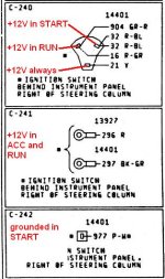
I installed a new HEI distributor and found that the "ignition" powered wire I was to use (which measures a full 12v w/key on) drop to .25 volts when I'm cranking the starter. Obviously this won't work. So how do you guys with HEI get a solid 12v power to the dizzy when key is "ON" and in "START"??
I have a '70 with a 351w and was happy to get rid of all that factory wiring. Now if I could only get it to run.%)
NOTE - I heard some guys use a switch between the battery and the dizzy, but I want to keep the dash, etc. as stock as possible. Thanks!
I have a '70 with a 351w and was happy to get rid of all that factory wiring. Now if I could only get it to run.%)
NOTE - I heard some guys use a switch between the battery and the dizzy, but I want to keep the dash, etc. as stock as possible. Thanks!