Dave, continuing to be a nice effort. You've done a great job deciphering this stuff.


Community
Message Forum
Photo Gallery
Event Calendar
Book Reviews
Bronco Wallpaper
Bronco FAQ
Link Back to CB!
Photo Gallery
Event Calendar
Book Reviews
Bronco Wallpaper
Bronco FAQ
Link Back to CB!
Buy / Sell


Bronco Tech
3 Arm Wiper Setup
Fix Motor Mount
Roll Cage Braces
Throttle Body 65mm
Wheel Alignment
Heat Riser Replacement
Vent Window Repair
Center Console Mount
Straighten Bumper
Ford 6R80 6 spd
More Tech...
Fix Motor Mount
Roll Cage Braces
Throttle Body 65mm
Wheel Alignment
Heat Riser Replacement
Vent Window Repair
Center Console Mount
Straighten Bumper
Ford 6R80 6 spd
More Tech...

Install the app
-
Welcome to ClassicBroncos! - You are currently viewing the forums as a GUEST. To take advantage of all the site features, please take a moment to register. It's fast, simple and absolutely free. So please join our community today!If you have problems registering or can't log into your account, please contact Admin.
You are using an out of date browser. It may not display this or other websites correctly.
You should upgrade or use an alternative browser.
You should upgrade or use an alternative browser.
OBD II Engine/Transmission Swap - The Next Generation
- Thread starter Dave
- Start date
Wyldebill
Full Member
Thanks Dave, I have been stalled for a while trying to decide which way to go on the ECM. With what you told me, I can proceed and buy a 2001 Explorer ECM and run the trans off of it s well. The AWD transfercase has already been scheduled for deletion, but as it has been mounted with a custom cross member and two brand new drive shafts, I decided to consentrate on the EFI hook up and get it through the inspections, (salvage title), before I put the 205 in it. I will aquire an EECV from an Explorer this week as I have already located one that is supposed to be out af 2001, but maybe it will turn out to be a 2000. I'll find out when I see it. Either one should be usable if my assumptions are correct. I did look up the autoenginuities web site, and just reading their info page cleared up a lot of my questions on what can be achieved with the EECV. The rig I am working on here is garaged in Longmont, so once I get my ECM bought, I'll get in touch and maybe I can run it over to Boulder so you can look it over and tell me if it will work.
Thanks Bill.
Thanks Bill.
OP
OP
- Joined
- Aug 25, 2006
- Messages
- 2,262
Thanks Dave, I have been stalled for a while trying to decide which way to go on the ECM. With what you told me, I can proceed and buy a 2001 Explorer ECM and run the trans off of it s well. The AWD transfercase has already been scheduled for deletion, but as it has been mounted with a custom cross member and two brand new drive shafts, I decided to consentrate on the EFI hook up and get it through the inspections, (salvage title), before I put the 205 in it. I will aquire an EECV from an Explorer this week as I have already located one that is supposed to be out af 2001, but maybe it will turn out to be a 2000. I'll find out when I see it. Either one should be usable if my assumptions are correct. I did look up the autoenginuities web site, and just reading their info page cleared up a lot of my questions on what can be achieved with the EECV. The rig I am working on here is garaged in Longmont, so once I get my ECM bought, I'll get in touch and maybe I can run it over to Boulder so you can look it over and tell me if it will work.
Thanks Bill.
Make sure you get the PATS that goes with that PCM.
OP
OP
- Joined
- Aug 25, 2006
- Messages
- 2,262
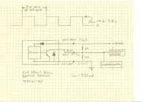
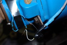
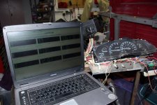
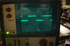
We have VSS signal!
Still waiting for the VSS to show up in the mail so I decided to build up a little circuit to validate my design. I stuck 4 magnets on the output yoke and used a reed switch to simulate the switching transistor in the Hall Effect sensor. The two resisters that create the voltage divider are under the shrink wrap. The signal levels work and both the speedometer and PCM are happy. ;D Probably not overly accurite but it proves the concept.
After a few seconds in gear the Transmission drive ratio bit transitioned to 1. I believe that this means that as long as the speedometer drive gear is correct for the tire size and differential ratio, the PCM learns the final drive ratio. I'm hoping that this happens on the fly so it will detect and compensate for low range. More learin to do.
Bottom line is: It pretty easy to eliminate the need for the ABS generated VSS signal by generating a VSS signal.
Please chime in if anyone knows anything about the ratio learned bit and the 4X4 low bit. There are absolutely no input signals to the PMC to tell it what state the transfer case is in. I would also like to find any tech info on the PMC software. I fear that it is still guarded propiritory information of FOMOCO or is that MOFOCO?
Attachments
Last edited:
OP
OP
- Joined
- Aug 25, 2006
- Messages
- 2,262
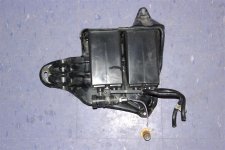
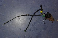
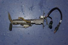
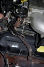
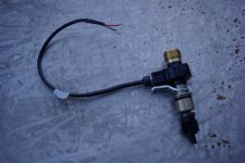
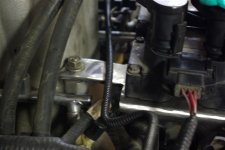
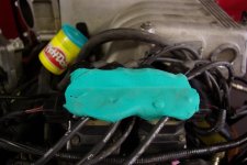
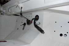
Fuel System
The fuel system is pretty simple. The first picture is the in tank pump module. It contains includes the fuel pump, fuel pick up filter, fuel pressure regulator, fuel level sensor, and fuel tank pressure sensor. The second picture is the fuel vapor purge valve which is used to suck vapors from the vapor canister and tank into the intake plenum. The last picture is of the vapor canister which includes the vent valve. This is the entire evaporative control system. I'll include a scematic and more explanation later.
The fuel system is pretty simple. The first picture is the in tank pump module. It contains includes the fuel pump, fuel pick up filter, fuel pressure regulator, fuel level sensor, and fuel tank pressure sensor. The second picture is the fuel vapor purge valve which is used to suck vapors from the vapor canister and tank into the intake plenum. The last picture is of the vapor canister which includes the vent valve. This is the entire evaporative control system. I'll include a scematic and more explanation later.
Attachments
OP
OP
- Joined
- Aug 25, 2006
- Messages
- 2,262
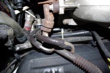
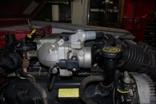
EGR System
Many have sited the differential pressure sensor (DPS) feedback EGR system as an impediment to using the Explorer induction system in swaps. It is true that it requires the OBD II computer to operate it and would not be compatible with an older electronic engine controllers (EEC). It does however, offer benefits in efficiency and performance.
EGR systems work by introducing an inert gas (exhaust gas) into the intake manifold. This lowers the specific heat capacity of the combustion mixture which means that less energy is available for conversion to mechanical energy. That's the negative. Reducing the specific heat capacity lowers combustion temperatures. Nitrous Oxides (NOx) are formed when nitrogen and oxygen are exposed to high temperatures and pressures. The purpose of the EGR is to reduce NOx emissions.
Early EGR systems on carbureted engines were simply controlled by vacuum. They were known for robbing power and decreasing economy. More sophistication was built into the controls which lead to a mass of vacuum lines, valves, timers, etc. They lead to a lot of vacuum leaks and failures. Disconnecting, bypassing, and removing these systems became that vogue thing to do.
The advent of electronic engine controls greatly improved the whole system. A proper working EGR system improves performance and economy while reducing NOx emissions. Thermal loss through the cylinder walls and heads is reduced by lower combustion temperatures which improves overall economy. Throttle loss is also reduced by requiring the throttle to be open more due to the added inert gas for a given power demand. This improves performance by decreasing the pressure in the intake. Kind of like trying to suck a bunch of air through a small straw. It takes power to pump that air into the engine which is reduced.
Proper operation of the EGR system requires just the right amount of inert gas to be introduced at the right time. Most engine controllers do not open the EGR valve a low power or high power demands. That is significant in that maximum output is obtained without any penalty from EGR. Engines over the past 10 years or so use a differential feedback system and a servo controlled EGR valve to accurately control the amount of inert gas delivered. Several other engine parameters such as timing and fuel schedule are controlled by the EEC that assumes the EGR is operating correctly. Disabling the EGR can lead to problems with drivability, efficiency, performance, running hot, failing emissions, and generating codes.
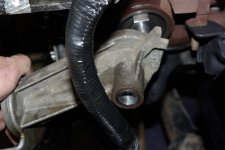
The differential pressure feedback measures the pressure on both sides of an orifice in the EGR tube that runs form the exhaust manifold to the intake manifold. You can see two hoses which connect the differential pressure sensor in the pictures below. The EEC (PCM) uses the DPS to verify EGR valve operation, calibrate the flow, and provide flow rates during operation.
The entire EGR system is contained within the engine and engine harness which is not disturbed in this installation. One more advantage of these more accurate engine controls is the elimination of that damn air pump and air induction system. Which is a real plus in fitting this engine into the Bronco. Air induction systems were used to burn the excess fuel in the exhaust that was added by the earlier EEC and carbureted engines to control emissions. If you donor engine had an air pump it most likely to running richer than necessary at the times the air induction system is engauged. Big issue? Probably not.
Many have sited the differential pressure sensor (DPS) feedback EGR system as an impediment to using the Explorer induction system in swaps. It is true that it requires the OBD II computer to operate it and would not be compatible with an older electronic engine controllers (EEC). It does however, offer benefits in efficiency and performance.
EGR systems work by introducing an inert gas (exhaust gas) into the intake manifold. This lowers the specific heat capacity of the combustion mixture which means that less energy is available for conversion to mechanical energy. That's the negative. Reducing the specific heat capacity lowers combustion temperatures. Nitrous Oxides (NOx) are formed when nitrogen and oxygen are exposed to high temperatures and pressures. The purpose of the EGR is to reduce NOx emissions.
Early EGR systems on carbureted engines were simply controlled by vacuum. They were known for robbing power and decreasing economy. More sophistication was built into the controls which lead to a mass of vacuum lines, valves, timers, etc. They lead to a lot of vacuum leaks and failures. Disconnecting, bypassing, and removing these systems became that vogue thing to do.
The advent of electronic engine controls greatly improved the whole system. A proper working EGR system improves performance and economy while reducing NOx emissions. Thermal loss through the cylinder walls and heads is reduced by lower combustion temperatures which improves overall economy. Throttle loss is also reduced by requiring the throttle to be open more due to the added inert gas for a given power demand. This improves performance by decreasing the pressure in the intake. Kind of like trying to suck a bunch of air through a small straw. It takes power to pump that air into the engine which is reduced.
Proper operation of the EGR system requires just the right amount of inert gas to be introduced at the right time. Most engine controllers do not open the EGR valve a low power or high power demands. That is significant in that maximum output is obtained without any penalty from EGR. Engines over the past 10 years or so use a differential feedback system and a servo controlled EGR valve to accurately control the amount of inert gas delivered. Several other engine parameters such as timing and fuel schedule are controlled by the EEC that assumes the EGR is operating correctly. Disabling the EGR can lead to problems with drivability, efficiency, performance, running hot, failing emissions, and generating codes.
The differential pressure feedback measures the pressure on both sides of an orifice in the EGR tube that runs form the exhaust manifold to the intake manifold. You can see two hoses which connect the differential pressure sensor in the pictures below. The EEC (PCM) uses the DPS to verify EGR valve operation, calibrate the flow, and provide flow rates during operation.
The entire EGR system is contained within the engine and engine harness which is not disturbed in this installation. One more advantage of these more accurate engine controls is the elimination of that damn air pump and air induction system. Which is a real plus in fitting this engine into the Bronco. Air induction systems were used to burn the excess fuel in the exhaust that was added by the earlier EEC and carbureted engines to control emissions. If you donor engine had an air pump it most likely to running richer than necessary at the times the air induction system is engauged. Big issue? Probably not.
Attachments
Last edited:
OP
OP
- Joined
- Aug 25, 2006
- Messages
- 2,262
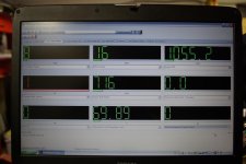
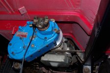
Vehicle Speed Signal (VSS) update
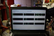
The Hall Effect speed sensor showed up today. If fits nicely in the D20 and pictured below. I wired it up as described in a previous post with the voltage divider resistors. I used a HEGO connector because they are sealed are about the right size. Fired it up and and checked the signal on the scope. Looks perfect. Both the PCM and speedometer read the same speed. Pcm speed is read with the scan tool. The only problem is the speed seems to be 1/2 of what it should be. I'm using a 20 tooth speedometer gear that I had laying around. The calculator I used for 3.73 gears and 255/70 R16 tires said a 18 tooth gear should be correct. The 20 tooth would should read about 10% low which does not account for the discrepency. 3000 rpms was reading about 35 mph. Should have been reading 70-80. Something isn't jiving with my assumptions. Somewhere my calculations are off by about 2X.
Update: Took the day off and went skiing and leave town for 3 days of work tomorrow. Monday I plan on chucking the VSS up in the lathe which has a digital tack so I can run it at a fixed speed. (1000 rpms = 60 mph) I know its putting out a correct signal but I wnat to verify that the digital speedometer and the PCM are seeing the correct speed. Kind of hard to do in the test stand. I'm expecting to see about 1/2 of what it should read. MSC said they would put a 16 tooth magnet in the unit I bought if I sent it back. The measurements I took on the 98 5.0 Explorer showed exactly 8000 pulses per minute at 60 mph. I double check that and try to determine if there were any changes between the 98 and 2000. Just another puzzle.
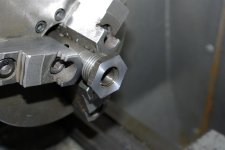
VSS Problem Solved
The erratic speed signal was being caused by the speedometer drive gear slipping on the output shaft of the D20. I had not torqued the yoke nut down because I had just put it on temporarily. Mostly to keep dirt out and oil in the transfer case. I stuck my finger in the speedometer drive hole and could spin the drive gear on the shaft. Tightened up the yoke nut and it works. Everything is happy and I feel kinda dumb but relieved.
The digital speed sensor uses a standard Ford speedometer drive gear. There are several web sites with gear calculators and tire size calculators but the formula is pretty simple.
1000 rpms is the standard for a speedometer to read 60 mph. 1000 revolutions also represents 1 mile traveled. You first need to know the effective diameter of the tires you are running. It will be slightly less than the size. The number is usually available from the manufacturer. The 255/70-16s I'm going to run have a effective diameter of 30.06 inches.
http://www.1010tires.com/tiresizecalculator.asp
30.06(in) X 3.14 (pi) / 12 (convert to feet) = 7.86 (feet per revolution)
5280 (ft per mile) / 7.86 (ft per revolution) = 671 (revolutions per mile)
Multiply that by your axle gear ratio: 671 X 3.73 = 2500 (rounded) drive shaft revolutions per mile.
The spedometer drive gear on the output shaft of the Dana 20 has a pitch of 7 which means it has 7 teeth across the face.
2500 X 7 = 1000 X (teeth on driven gear) or 17,500 / 1000 = 17.5 teeth. The closest speedometer gear is a 18 tooth.
A drive shaft speed of 2500 rpms at 60 mph would yeild of engine speed of 2500 X .7 (OD) = 1750 rpms. That is the stock gearing in the Explorer which works well on the highway. My 98 5.0L explorer gets about 20 mpg on the many roadtrips back and forth to Michigan. Pulling a light camper doesn't seem to effect it much. We usually cruise the speed limit of 75 mph. It is a 2WD. I don't intend on cruising quite that fast with the Bronco and am planning on going with 4.11s and ARBs (someday).
I've got a set of axles out of a 72 with 3.73 and factory L/S froont and rear. I'm going to use them initially and see how thing work out.
With 4.11 gears: 671 (from above) X 4.11 = 2758 2758 X .7 (OD) = 1930 rpms @ 60 mph in over drive.
35s and 4.56 example:
33.5 X 3.14 / 12 = 8.76 5280 / 8.76 = 602.3 X 4.56 = 2746.6 2746.6 X 7 = 19.226 19226.6 / 1000 = 19 tooth Speedo gear.
Transfer Case Selection: I'm obviously using the Dana 20 on my installation. You will need a transfer case with a speedometer drive. The Explorer AWD and 4WD transfer cases have the casting features but they are not machined out. Another VSS option is a inline VSS whch would screw on to the back of the speedometer or in the middle of a custom cable (atlas). Either case requires the drive on the transfer case. I believe the transfere cases on pre 97 Explorers have a VSS if you want to use one of those cases. A 205 would work also. Keep in mind that the 4WD case on the Explorer is electronically shifted by the general electronics module (GEM) It would be a challenge to wire that into the system as it controls just about everything else in the vehicle. (It has about 3 million wires hooked to it)
The Hall Effect speed sensor showed up today. If fits nicely in the D20 and pictured below. I wired it up as described in a previous post with the voltage divider resistors. I used a HEGO connector because they are sealed are about the right size. Fired it up and and checked the signal on the scope. Looks perfect. Both the PCM and speedometer read the same speed. Pcm speed is read with the scan tool. The only problem is the speed seems to be 1/2 of what it should be. I'm using a 20 tooth speedometer gear that I had laying around. The calculator I used for 3.73 gears and 255/70 R16 tires said a 18 tooth gear should be correct. The 20 tooth would should read about 10% low which does not account for the discrepency. 3000 rpms was reading about 35 mph. Should have been reading 70-80. Something isn't jiving with my assumptions. Somewhere my calculations are off by about 2X.
Update: Took the day off and went skiing and leave town for 3 days of work tomorrow. Monday I plan on chucking the VSS up in the lathe which has a digital tack so I can run it at a fixed speed. (1000 rpms = 60 mph) I know its putting out a correct signal but I wnat to verify that the digital speedometer and the PCM are seeing the correct speed. Kind of hard to do in the test stand. I'm expecting to see about 1/2 of what it should read. MSC said they would put a 16 tooth magnet in the unit I bought if I sent it back. The measurements I took on the 98 5.0 Explorer showed exactly 8000 pulses per minute at 60 mph. I double check that and try to determine if there were any changes between the 98 and 2000. Just another puzzle.
VSS Problem Solved
The erratic speed signal was being caused by the speedometer drive gear slipping on the output shaft of the D20. I had not torqued the yoke nut down because I had just put it on temporarily. Mostly to keep dirt out and oil in the transfer case. I stuck my finger in the speedometer drive hole and could spin the drive gear on the shaft. Tightened up the yoke nut and it works. Everything is happy and I feel kinda dumb but relieved.
The digital speed sensor uses a standard Ford speedometer drive gear. There are several web sites with gear calculators and tire size calculators but the formula is pretty simple.
1000 rpms is the standard for a speedometer to read 60 mph. 1000 revolutions also represents 1 mile traveled. You first need to know the effective diameter of the tires you are running. It will be slightly less than the size. The number is usually available from the manufacturer. The 255/70-16s I'm going to run have a effective diameter of 30.06 inches.
http://www.1010tires.com/tiresizecalculator.asp
30.06(in) X 3.14 (pi) / 12 (convert to feet) = 7.86 (feet per revolution)
5280 (ft per mile) / 7.86 (ft per revolution) = 671 (revolutions per mile)
Multiply that by your axle gear ratio: 671 X 3.73 = 2500 (rounded) drive shaft revolutions per mile.
The spedometer drive gear on the output shaft of the Dana 20 has a pitch of 7 which means it has 7 teeth across the face.
2500 X 7 = 1000 X (teeth on driven gear) or 17,500 / 1000 = 17.5 teeth. The closest speedometer gear is a 18 tooth.
A drive shaft speed of 2500 rpms at 60 mph would yeild of engine speed of 2500 X .7 (OD) = 1750 rpms. That is the stock gearing in the Explorer which works well on the highway. My 98 5.0L explorer gets about 20 mpg on the many roadtrips back and forth to Michigan. Pulling a light camper doesn't seem to effect it much. We usually cruise the speed limit of 75 mph. It is a 2WD. I don't intend on cruising quite that fast with the Bronco and am planning on going with 4.11s and ARBs (someday).
I've got a set of axles out of a 72 with 3.73 and factory L/S froont and rear. I'm going to use them initially and see how thing work out.
With 4.11 gears: 671 (from above) X 4.11 = 2758 2758 X .7 (OD) = 1930 rpms @ 60 mph in over drive.
35s and 4.56 example:
33.5 X 3.14 / 12 = 8.76 5280 / 8.76 = 602.3 X 4.56 = 2746.6 2746.6 X 7 = 19.226 19226.6 / 1000 = 19 tooth Speedo gear.
Transfer Case Selection: I'm obviously using the Dana 20 on my installation. You will need a transfer case with a speedometer drive. The Explorer AWD and 4WD transfer cases have the casting features but they are not machined out. Another VSS option is a inline VSS whch would screw on to the back of the speedometer or in the middle of a custom cable (atlas). Either case requires the drive on the transfer case. I believe the transfere cases on pre 97 Explorers have a VSS if you want to use one of those cases. A 205 would work also. Keep in mind that the 4WD case on the Explorer is electronically shifted by the general electronics module (GEM) It would be a challenge to wire that into the system as it controls just about everything else in the vehicle. (It has about 3 million wires hooked to it)
Attachments
Last edited:
OP
OP
- Joined
- Aug 25, 2006
- Messages
- 2,262
Test Video
Here's my first attempt at a youtube video. I'm hoping to post some diagnostic clips with the OBDII scan tool. This is just a shot of the engine running in the stand.
[youtube]E7nnYINIXDA[/youtube]
I hope people are finding this information usefull. I'm done with the engine tinkering and am getting ready to drop it in the frame. The build up process should go pretty fast. The frame is media blasted and ready for paint. The tub is primed, undercoated (Raptor), and is ready to drop on the frame. I'm looking forward to the next phase. I'll post some pictures as I go. Let me know if anyone would like to see more information on the engine and controls. I'll continue documentation on the harness as I incorporate it into the Bronco.
Dave...
Last edited:
OP
OP
- Joined
- Aug 25, 2006
- Messages
- 2,262
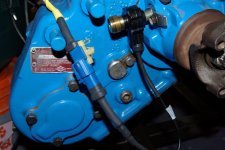
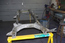
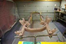
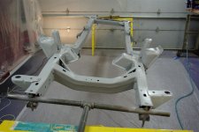
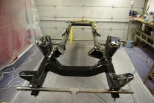
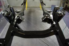
Frame Prep
Got the frame media blasted about a year ago. I touched up some of the factory welds that missed the seam and cleaned up the splatter. Since it has sat for about a year I thought it would be a good idea to go with an etching primer. First coat - Etching primer. Second coat - 2K epoxy primer/sealer. Would have just used a bare metal primer but I had some stock to use up. Eastwood 2K ceramic chassis black (statin) is next. 1 quart was perfect for the two wet coats on the frame. I did thin the second batch with 10% urethane reducer for a little better flow out. I still have 1 quart left for the axles, radius arms, etc. I ordered this about 6 months ago and the solids settled. It was a bitch to get them back into solution with a paddle. Next quart is going down to the local paint shop for good shakin. I'm real happy with the way it sprayed and looks.
Got the frame media blasted about a year ago. I touched up some of the factory welds that missed the seam and cleaned up the splatter. Since it has sat for about a year I thought it would be a good idea to go with an etching primer. First coat - Etching primer. Second coat - 2K epoxy primer/sealer. Would have just used a bare metal primer but I had some stock to use up. Eastwood 2K ceramic chassis black (statin) is next. 1 quart was perfect for the two wet coats on the frame. I did thin the second batch with 10% urethane reducer for a little better flow out. I still have 1 quart left for the axles, radius arms, etc. I ordered this about 6 months ago and the solids settled. It was a bitch to get them back into solution with a paddle. Next quart is going down to the local paint shop for good shakin. I'm real happy with the way it sprayed and looks.
Attachments
Last edited:
OP
OP
- Joined
- Aug 25, 2006
- Messages
- 2,262
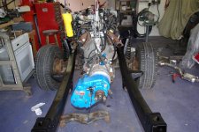
Engine In Frame
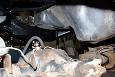
I put the old axles and my new WH springs under the frame and just dropped the engine and tranny in. The Explorer oil pan looks like it was made for the Bronco. Real nice fit. That's the D30 I've got is sitting on for now. I've got a EB D44 that is pretty rust pitted and a couple of D44 HPs. I'm going to probably make up a Frankenaxle out of the bunch. I'd like to use the HP but am assumeing clearence problems with the stock lift. I might pop the tubes out of the EB D44 and stick in the HP tubes. Thanks to Michigan salt the rust pitting is as bad as you could imagine on axles that I harvested out of a 72. I dont think the wedges would hold the C-bushings and the bump stop perches are about rotted off.
I put the old axles and my new WH springs under the frame and just dropped the engine and tranny in. The Explorer oil pan looks like it was made for the Bronco. Real nice fit. That's the D30 I've got is sitting on for now. I've got a EB D44 that is pretty rust pitted and a couple of D44 HPs. I'm going to probably make up a Frankenaxle out of the bunch. I'd like to use the HP but am assumeing clearence problems with the stock lift. I might pop the tubes out of the EB D44 and stick in the HP tubes. Thanks to Michigan salt the rust pitting is as bad as you could imagine on axles that I harvested out of a 72. I dont think the wedges would hold the C-bushings and the bump stop perches are about rotted off.
Attachments

Last edited:
OP
OP
- Joined
- Aug 25, 2006
- Messages
- 2,262
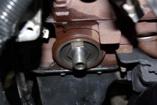
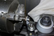
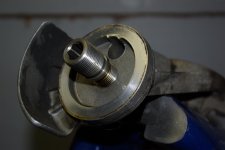
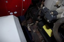
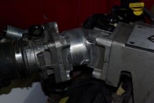
Oil Filter
The Explorer uses an aluminum goose neck to relocate the oil filter to point forward just below the fan. This hits the front cross member. The oil filter nipple in the engine block has inside threads for the bolt that hold the goose neck on. Viperwolf1 sent me the part number for the correct nipple to screw the filter directly on to the block. ("F1AZ-6890-B, about $6") Or the one out of your old engine would probably work.
I called around and couldn't find one without special order so I modified the parts from the goose neck to work. Turns out that the nipple on the filter end of the goose neck will screw into the nipple on the engine. It was a little long so I had to cut it down. Took about 20 minutes in the lathe but saved me a week wait for UPS or some junk yard dumpster diving. Hope to have some pictures of the tub on in a couple of hours.
Speaking of UPS: Has anyone else noticed that UPS ground is taking forever. I used to get parts in 3 or 4 days. Now UPS ground is running better than a week. 8 Days in transit for the speed sensor. Ordered some hardware last Thursday morning from WH. Shipped that afternoon. Delivery is scheduled for Friday.
Attachments
Last edited:
OP
OP
- Joined
- Aug 25, 2006
- Messages
- 2,262
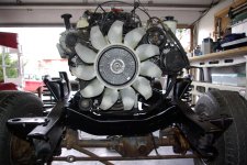
Serp Belt
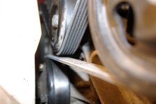
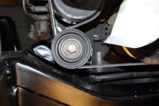
I've been running the engine with the AC pump in place. It looks like it would fit but I don't intend on using it. Pulled it off and fit up a new belt. The stock belt is 93.5 inches long with AC. 82.5 inches without. (Gates part number K060825) The belt passes within about 1/4 inch of itself as it goes around the power steering pulley. Should not cause any rubbing problems. The bottom idler pulley clears the cross member if the tail of the transmission is not raised too high. Keep that in mind when lifting the rear of the tranny or dropping the engine in. Might be a good idea to pull it off for installation.
I did leave the wires and connectors in place for the AC clutch in case I ever change my mind or figure out some way to mount an air pump there.
Attachments
- Joined
- Aug 23, 2007
- Messages
- 24,337
I've been running the engine with the AC pump in place. It looks like it would fit but I don't intend on using it. Pulled it off and fit up a new belt. The stock belt is 93.5 inches long with AC. 82.5 inches without. (Gates part number K060825) The belt passes within about 1/4 inch of itself as it goes around the power steering pulley. Should not cause any rubbing problems.
I've run the shorter belt without the AC compressor for several thousand miles and have not seen any problems.
RnrdTheFox
Sr. Member
The Explorer uses an aluminum goose neck to relocate the oil filter to point forward just below the fan. This hits the front cross member. The oil filter nipple in the engine block has inside threads for the bolt that hold the goose neck on. Viperwolf1 sent me the part number for the correct nipple to screw the filter directly on to the block. ("F1AZ-6890-B, about $6") Or the one out of your old engine would probably work.
I called around and couldn't find one without special order so I modified the parts from the goose neck to work. Turns out that the nipple on the filter end of the goose neck will screw into the nipple on the engine. It was a little long so I had to cut it down. Took about 20 minutes in the lathe but saved me a week wait for UPS or some junk yard dumpster diving. Hope to have some pictures of the tub on in a couple of hours.
Most of the explorer engines I've seen actually had an oil cooler instead of the goose neck like you have. The return line from the radiator was run through it to cool the oil. It still has the clearance issues with the frame though. I ended up putting a remote oil cooler off a 90's 460 F250 engine and using it. It bolts right to the nipple on the block and turns the filter straight down so it's easy to get to. Then I put an oil cooler between the frame rails.
OP
OP
- Joined
- Aug 25, 2006
- Messages
- 2,262
Tub on for trial fit
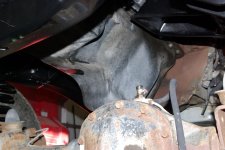
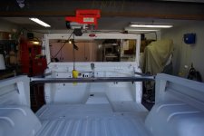
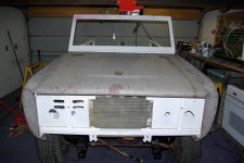
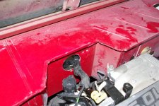
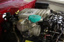
Got the tub on single handed. The overhead crane made that very easy. It's sitting on a 1 inch body lift. Everything clears well. The airbox fits nicely in the origional battery postion. The battery will bo on the drivers side which accomodates the existing wires on the engine. so far it looks like the only hood issue is going to be the Idle air valve and the induction tube. I'm looking at options that include fabricating an angled adaptor to move the throttle body away and down from it's oritional position. A hood scoop would solve any issues but would detract from the stock look.
I checked the clearence between the hood and coils and found another issue. I cut 1 1/4" off the legs of the coild support bracket and welded it back together. You can easliy lower the coils without interfearing with anything else. I should have also tilted it forward a bit for more clearence. I may find another bracket and do it. It's real close between the front row of plug wires and the support in the hood. I also raised the tail of the transmission a bit more which will help. I really wanted to keep the engine in a bone stock configuration but these mods are pretty easy and benign.
Attachments
-
 Frame 038 (Large).jpg100.8 KB · Views: 155
 -
 Frame 035 (Large).jpg59.3 KB · Views: 154
 -
 Frame 034 (Large).jpg118.1 KB · Views: 201
 -
 Frame 033 (Large).jpg92.6 KB · Views: 185
 -
 Frame 032 (Large).jpg72.9 KB · Views: 136
 -
 Frame 039 (Large).jpg87 KB · Views: 131
 -
 Frame 044 (Large).jpg95.3 KB · Views: 166
 -
 Frame 043 (Large).jpg89.2 KB · Views: 174
 -
 frame 101 (Large).jpg64.3 KB · Views: 160
 -
 frame 099 (Large).jpg75.2 KB · Views: 180
Last edited:
OP
OP
- Joined
- Aug 25, 2006
- Messages
- 2,262
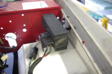
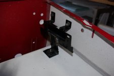
Harness Installation
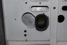
I decided to install the connectors behind the dash instead of in the engine compartment. Should keep everything very clean in the engine compartment.
I'll punched a 3 inch hole so the PCM and and block connector will fit through the firewall. I'll make a 2 piece polished plate with with a grommet to cover the hole and the other unused holes.
I'll post more pictures and text here as I go.
Attachments
OP
OP
- Joined
- Aug 25, 2006
- Messages
- 2,262
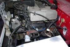
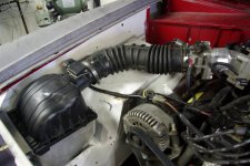
Got Her Stuffed!
Got the Explorer engine stuffed under the stock hood. The easy way would have been a hood scoop and I really like the dress of the Explorer engine but this worked out well.
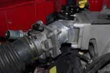
Made a junk yard run yesterday. They had two 99 5.0 Explorers down there that someone had pulled the intake maniforlds from. They left the 90 degree elbows between the manifold and throttle body. I grabbed them and cut the flanges off one and weld in a straight tube to point the throttle body 45 degrees forward and about 15 degrees down.
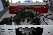
The inside transitions came out very smooth and I eliminated one 90 elbow from the stock configuration. I'm going to have to fabricate a new bottom for the air box with a inlet pointing forward. When I get all of the pieces mounted the tub will come back off or final paint. I was going to be Amulet Red thus the tinted Raptor on the underside. New color is going to be Electric Blue Metalic and Pepper White. Colors of the neighbors Mini that I really like.
Back to work tomorrow for 5 days on the road :-[
Got the Explorer engine stuffed under the stock hood. The easy way would have been a hood scoop and I really like the dress of the Explorer engine but this worked out well.
Made a junk yard run yesterday. They had two 99 5.0 Explorers down there that someone had pulled the intake maniforlds from. They left the 90 degree elbows between the manifold and throttle body. I grabbed them and cut the flanges off one and weld in a straight tube to point the throttle body 45 degrees forward and about 15 degrees down.
The inside transitions came out very smooth and I eliminated one 90 elbow from the stock configuration. I'm going to have to fabricate a new bottom for the air box with a inlet pointing forward. When I get all of the pieces mounted the tub will come back off or final paint. I was going to be Amulet Red thus the tinted Raptor on the underside. New color is going to be Electric Blue Metalic and Pepper White. Colors of the neighbors Mini that I really like.
Back to work tomorrow for 5 days on the road :-[
Attachments

Last edited:
OP
OP
- Joined
- Aug 25, 2006
- Messages
- 2,262
Air Box
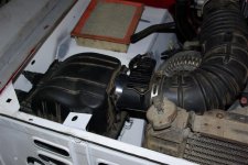
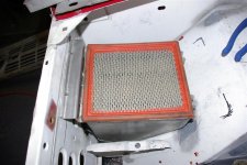
Took some time and built up a press break so I could make some sheet metal parts. The stock Explorer airbox could have been modified by trimming a bit off the bottom and glassing or riviting a sheet metal botom on it. The one I built is overkill but I wanted to get some practice with .125 5052 Aluminum as that is what I'm going to build my gas tank out of. I got some beautiful welds and some not so great ones. I did learn a bunch but am going to practice a bit more and work on some technique. Clean clean clean and go slow. I'll clean it up a bit and powder coat it black. The intake location is about identical to the Explorer. Should be plenty of room for airflow and maybe some ram effect on the road. The airbox is easy to remove so getting at the headlight plug will not be too much of a hastle. It should be shielded from direct intake of rain and snow. If it were going to see abusive use in water I would probably snorkle the intake up to the top of the grill.
Took some time and built up a press break so I could make some sheet metal parts. The stock Explorer airbox could have been modified by trimming a bit off the bottom and glassing or riviting a sheet metal botom on it. The one I built is overkill but I wanted to get some practice with .125 5052 Aluminum as that is what I'm going to build my gas tank out of. I got some beautiful welds and some not so great ones. I did learn a bunch but am going to practice a bit more and work on some technique. Clean clean clean and go slow. I'll clean it up a bit and powder coat it black. The intake location is about identical to the Explorer. Should be plenty of room for airflow and maybe some ram effect on the road. The airbox is easy to remove so getting at the headlight plug will not be too much of a hastle. It should be shielded from direct intake of rain and snow. If it were going to see abusive use in water I would probably snorkle the intake up to the top of the grill.
Attachments

Last edited:
OP
OP
- Joined
- Aug 25, 2006
- Messages
- 2,262
very sexy Dave!
Thanks! Now for an equally sexy battery box for the other side.;D
Similar threads
- Replies
- 3
- Views
- 745