


C6-203-205 Doubler
Tech article by admin and filed under Transfer CaseThe bolt itself I chose to lock into place with a jam nut which would allow me to adjust how tight the shifter would be mounted. For the shifters I chose to use a small chunk of heavy bar (About 3/4″ x 1 1/4″) which I cut into 3 pieces that are each about 1 1/4″ long. This created 3 blocks that were approx. square on one side and were about 3/4″ thick. I then drilled holes in the center of each of them to fit the bolt going into the transmission boss. If I recall right the bolt is 9/16″ by approx. 3 1/2″ or 4″ long. Then I drilled and tapped a 1/2 course thread hole in the end of each of them to fit 3 pieces of 1/2 rod with the ends threaded to fit. I started with about 18″ long on each rod which I would then cut off to the desired length once I had everything installed in my Bronco. On the opposite end of each of the blocks I then welded 3 pieces of metal bar that were about 1/4″ x 1 1/4″ by approx. 3″. This gave me the basic shifter assembly that would pass through the floorboard. I then got to work on the NP 205 transfer case. I first made the shifter modifications that would be required to make the NP 205 a twin stick. This required removing one of the shafts and grinding 2 small areas on it to allow the shifters to work independently without allowing it to be shifted into high and low range at the same time.


NP 205 Twin Stick shifter shaft mods.
Next I had to decide how to make the inside shifter work on the NP 205 since it sits behind the adapter and can’t be shifted directly with a shift rod. I settled on a bell crank setup with a bracket and arm that would reach back behind the adapter and allow the shift rod to connect next to the outer one. While I was at it I added a small plate to the outer shifter to connect the rod ends I settled on for linkage between the shifters and the shifter shafts.

NP 205 shifter bracket and bell crank.
At this point I had mocked up the shifter linkage and added the 5/16″ rod I chose for linkage between the shifters and the transfer cases with the ends threaded for 5/16″ rod ends.
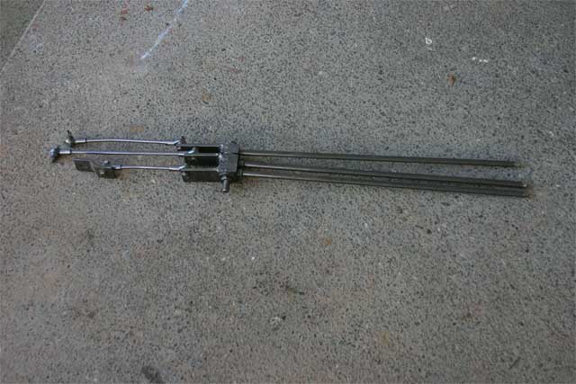
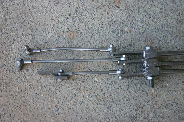
Basic triple stick shifter assembly prior to final trimming and knob installation.
After working out the details of the triple stick shifters I removed all of the gears from the NP 205 transfer case both to inspect them and to remove a lot of weight from it so I could handle it easier underneath while I figured out where I would clock it up so I could weld the adapter together. I then bolted in the C6 transmission followed by the NP 203 range box. Neither of these would need to be removed once they were installed so I cleaned them up and added transmission fluid to the torque converter before I installed them. I used Blue RTV to seal the surfaces between the C6 and the NP 203. Once in position I ran a bar underneath them across my radius arms to hold them up until I could build the cross member.

C6 and NP 203 installed and held in place prior to installing the cross member.
Next I put the 203 to 205 adapter plate on and bolted it to the back of the NP 203 and did the same with the NP 205 side as well. I then put the NP 205 up there and made adjustments to it until I was happy with how it fit. The adapter pieces slide together enough to support the empty NP 205 case which I was careful to keep up against the NP 203. (Even with it empty it would hurt if it fell on you) My final position was with the NP 205 clocked up into position with the bottom of it slightly higher than the bottom of the NP 203. This put the left side fairly flat against the left frame rail. With a little persuasion I moved the back over slightly to get about a 1/4″ gap between the NP 205 and the left frame rail. When you do this look at the front driveline position (Don’t forget the transmission and transfer case linkage that also needs to go through there) and check the clearance at the front of the motor so the fan doesn’t end up in the radiator. It may be worth noting at this point that I do have a 3″ body lift. Without it I think the floorboard would need some changes. The idea of putting it up high was to get as much clearance underneath as possible and allow me to later install a skid plate. (More on this later) Once I was happy with the position I marked the adapter so I could remove it and then weld the two pieces together. The instructions suggested using a shop press to apply 150 lbs. or so of pressure when welding the 2 together. I substituted a heavy NP 205 transfer case instead which I set on top of it when I made the initial tack welds around it.

NP 203 to NP 205 adapter after welding and painting.
Following the welding I assembled the NP 205 transfer case using the new seal kit. A tip when putting the needle bearings in is to use engine assembly grease to keep them in place while your putting it together. I then painted the transfer case prior to installing it.

NP 205 transfer case ready for final installation.
I then bolted the Adapter and the NP 205 transfer case in. I again used Blue RTV to seal the surfaces and discarded the gasket that came with the NP 205 seal kit. For this application the RTV works better than the gasket.
With all of the pieces now underneath my next task was to fabricate the cross member. My initial cross member basically consisted of two 1 1/2″ x 1/4″ bars running under the frame with a piece of angle on each end. In the front I used the original C6 transmission mount which already had a rubber bushing and in back I dug up some shock bushings as a temporary setup until I could pick up some better bushings. This is the one item I went back and later changed since I wasn’t happy with how it worked out. (More on this later)

Original Cross Member.
With everything bolted in now I went to work on the shifters for both the transfer cases and the transmission. The transfer case shifters bolted right in with a a few bends in them to position them through the original hole in the floorboard which I trimmed to be about 2 inches wider. I then cut the extra length of 1/2″ rod off to a height that would allow me to shift them without breaking my knuckles on the dash. I then threaded each one with 1/2″ threads to fit some plain black knobs. Wild Horses sells shifter knobs with the patterns on them except that the crawler knob they sell has the pattern backwards for this setup. I use mine enough that I have the patterns memorized so I haven’t worried about getting knobs with shift patterns on them.
My next task was to install the shifter for the transmission. My previous C4 had a Hurst shifter for it which I always hated because of the way the reverse lockout worked. I decided to go shopping and picked up a B&M Truck Megashifter. It sits higher and fits nicely next to the drivers seat. Between 1st and Drive it works as a ratchet shifter which is nice for manually shifting while climbing dunes for instance and the reverse lockout all works from the T handle using one hand. I.E. I can pull the lockout up and shift back and forth between drive and reverse without using 2 hands. It has a light for the positions at night and includes micro switches for the neutral safety switch and the backup lights. (One of these days I’ll wire the switches in) During the installation I ran into a problem though. The Shifter bracket that connect the cable to the transmission stuck out too far and was sure to get hit by the front driveline. To fix this I modified the bracket so it sits in a higher position that doesn’t stick out as far.

Modified transmission shifter cable bracket.

Transmission Shifter and Triple stick shifters installed.
June 13th, 2010 at 12:22 pm
How is the rear drivehsaft angle on this? Do you have any measurements?
Thanks