• Welcome to ClassicBroncos! - You are currently viewing the forums as a GUEST. To take advantage of all the site features, please take a moment to register. It's fast, simple and absolutely free. So please join our community today!
    If you have problems registering or can't log into your account, please contact Admin.

Engine Swap: Cummins R2.8

OP
OP
Digger556

Digger556

Sr. Member
Joined
Aug 8, 2013
Messages
793
Any updates, I was curious to see if you wire the cummins to the factory gauges. I will be starting a build with that engine soon.

I have been working on it here and there, but family priorities and other projects have forced a hold on work. I'll try to get some pictures up soon.

Not sure I will be much help on the gauges, I have Dakota Digital setup. However, the Cummins has ports for both water temp and oil pressure. You should be able to use factory Ford sensors by extending some wires and using a few NPT adapters to get your factory gauges hooked up.
 
OP
OP
Digger556

Digger556

Sr. Member
Joined
Aug 8, 2013
Messages
793
Whew, 5 months since my last update!

Needless to say, there has been A LOT going on in my life. Too much for details. Other things needed more attention than the Bronco. Summer came and went before I knew what happened. Things are getting back to normal and the push on the Bronco has resumed.

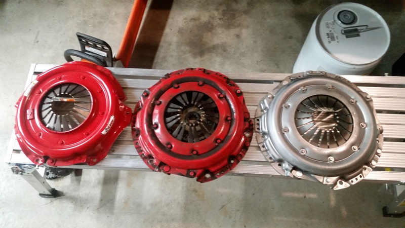
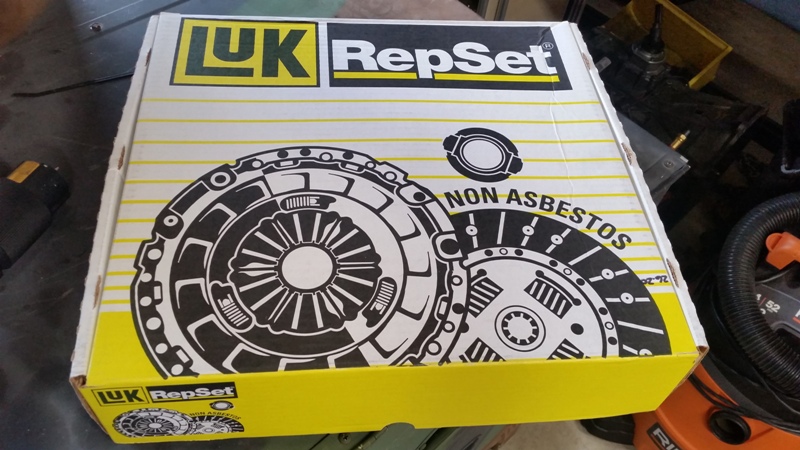
Going back to early May, I ordered a clutch for the R2.8. Nothing special, just another McLeod like the unit I had before. I could have re-used the old one, but it was grooved and I wanted fresh parts. Well that started another fiasco similar to the intake manifold problem I had last summer that started this whole engine swap. I was getting a pit in my stomach at the prospect of waiting months for back ordered parts. I was able to track down a different clutch kit and order it. Well it showed up and it was definitely not designed for a hydraulic throw out bearing. So I jumped brands and bought a Luk clutch kit that seems like it will fit the build. Nothing fancy, just a standard clutch with a little extra holding power.

48912375432_7e1125bdc0_o.jpg


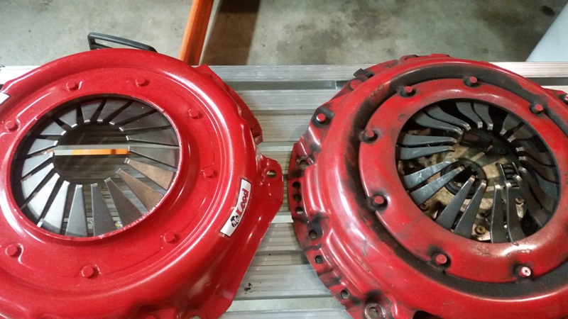
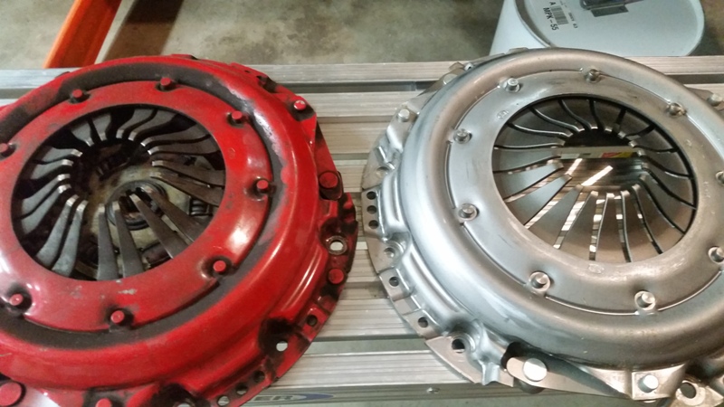
Laying all three clutches side-by-side, you could see the difference in the spring fingers. The new McLeod clutch fingers did not extend as far towards the crank centerline and the hydraulic throwout bearing wanted to pass right through. Additionally, the distance from pressure plate to top of clutch fingers was slightly different.
48912375402_dcc59d65ce_o.jpg

48912165431_cf94c65ce7_o.jpg

48912375367_cfb7619e49_o.jpg


Ironically, all three pressure plates were stamped "Luk".


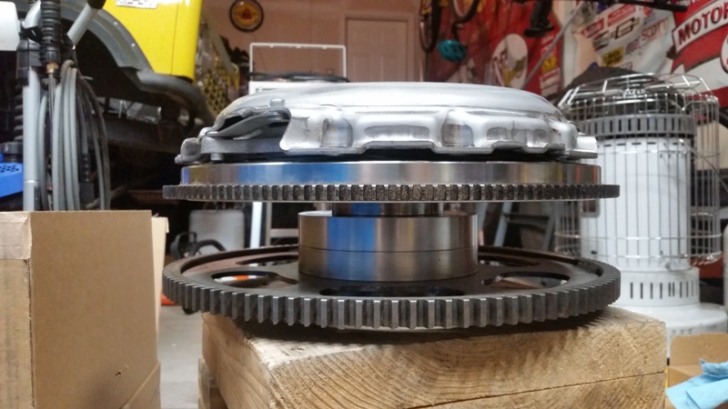
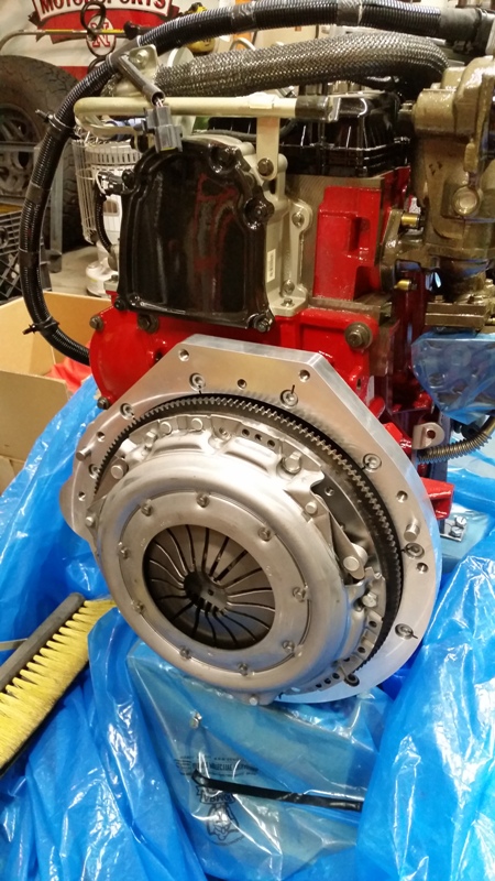
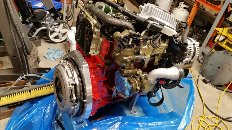
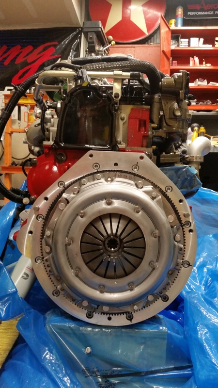
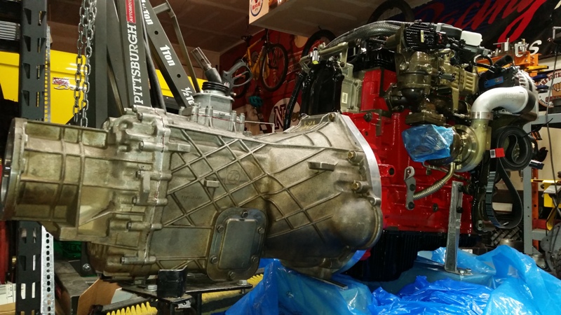
With new clutch in hand, about mid-June, I dis-assembled the adapter set and fit the clutch.
48911642598_557298179b_o.jpg


The stack of parts is pretty tall, not ideal, but it should work fine. Weight-wise, its heavy. Both the stock Ford 351 flywheel and the Cummins flywheel hover around 25lbs. The stack with adapters is pushing 45lbs. However, the majority of that weight is much closer to the crank centerline, so additional rotational inertia is minimized. Add the clutch set in the mix and I don't think the impact will be too bad. Some guys have stacked two flywheels weighing over 60lbs with adapters, so I'll be okay.

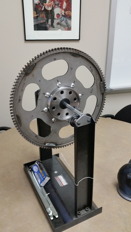
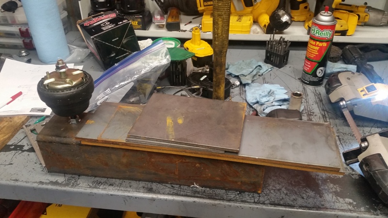
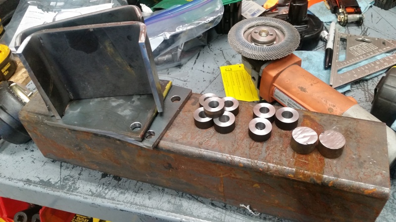
The main reason for pulling the adapter was to check balance on my flex plate. The adapters themselves don't really need a balance, as they are very true and closer to crank centerline. Maybe someday when I build my dynamic balancer, I'll throw in the whole thing on.

To check balance on the flex plate, I borrowed a motorcycle wheel balancer. Since the flexplate has a high diameter:length ratio, a static balance is good enough. A few of us at work played with it for a while, but the unit was very true and well balanced, so no weight was removed. We double checked our selves by adding weight at different points to verify the unit was truly balanced with the weight removed.
48912375327_2901399a7e_o.jpg
 
OP
OP
Digger556

Digger556

Sr. Member
Joined
Aug 8, 2013
Messages
793
Thanks to the CAD model Bronco, I knew going in that the Diesel Oxidation Catalyst (DOC) would not fit between the engine and frame rail. I do intend to keep it and maintain the emission equipment, but it will need to be moved downstream a bit. Originally I planned to use a different turbo exhaust elbow from another 2.8 ISF application, but after studying the CAD model, decided it would be easier to route the exhaust like the passenger side of the 351. There was no off-the-shelf turbo outlet for this, so I drew up a flange in SolidWorks and printed out the template.
48912375312_8652a556b0_o.jpg


Comparing it to the old turbo outlet, it looked correct. A friend of mine cut the flange out on his waterjet. I neglected to get a picture, but it fit perfect. More on that later when I build the exhaust.
48911642553_8ac0f25c25_o.jpg


With flexplate balance confirmed, it was time for the FINAL assembly. I installed the pilot bearing. Fitment was very good.
48911642538_670d669f17_o.jpg


I researched and calculated all the torque specs based on known tables and my experience at work with bolt testing. It's pretty interesting stuff if you want to "dork out" for a while. Bolt finishes have an impressive impact on torque specs. All bolts were loctite'd and torqued down, then marked.
48912165326_b0f2c6ccb4_o.jpg


Clutch installed:
48911642508_3cb7905e7d_o.jpg

48911642468_52ab04fb32_o.jpg

48912375207_ebf2f32cf1_o.jpg


Before attempting to install the engine, I pulled my spare ZF-5 to verify the transmission will bolt up without issue. It went pretty smoothly, but the transmission would not slide all the way together with the engine adapter. Fearing the worst, I pulled the clutch and re-assembled it, taking great care to center up the friction disc. Still a No-Go. The transmission did not want to slide the last 1/8". I pulled it apart again, but removed the clutch. BOOM, transmission slide right into place. OKAY, now I know it's not the adapter or pilot bearing.

I played with the clutch some more and determined the input shaft just really fits tight on the friction plate splines. A minor amount of help from the transmission mounting bolts and the two pulled right into place.
48912165246_68b413a344_o.jpg


It was really exciting to see the two mated up for the first time!
48912165206_b5fe1ff449_o.jpg

48912165191_0a846278b4_o.jpg
 
OP
OP
Digger556

Digger556

Sr. Member
Joined
Aug 8, 2013
Messages
793
With a free Saturday, I headed over to U-Pull-n-Pay to scout for some parts. I ended up pulling the air filter box from a V8 Explorer of all applications.
48912165176_ea3abfb3ac_o.jpg


I'll need to fabricate a hose to flange adapter to replace the MAF, but that will be okay.
48912375117_82ee96c98a_o.jpg


Back home, I spent a few evenings researching motor mounts. I wanted to re-use the existing frame mounts and MAYBE OEM motor isolators. But it just wasn't going to work. SO, I looked around and discovered most Cummins swap guys are using canister type isolators with threaded studs protruding from each end. It's a straight-forward way to mount the engine. My goal is to use as many OEM parts as possible to improve service-ability. The canister-type mounts have been used by many brands, but it turns out Ford used them on 300 I6's in the last 80s/early 90s. So a trip to the parts store and I bought a set.

After modeling them up in Solidworks, I imported them into the big model and began designing the mounting brackets. This took a few evenings. In the end, I tried to mimic a cast bracket with a weldment. I ran some stress analysis on the brackets and tweaked them a bit, but in the end I have brackets that will withstand a 4G vertical loading with a 1.5 safety factor. 4G was chosen because that is near the upper limit of the suspension brackets before deformation could start to occur. I've hit 3Gs a couple of times and the spring buckets were designed with 5Gs in mind.

Back in the garage, starting with raw stock:
48912375082_f99f586d9e_o.jpg


I bent up the brackets and turned the mounting bosses:
48912165116_cb975c7ab4_o.jpg


Drilling holes:
48912375062_4e20e58147_o.jpg


Welded up. Certainly not my best work, but functional:
48912375037_3f8beac7d5_o.jpg


Painted and isolators thrown on:
48912165081_fc04eb96c2_o.jpg


On to the frame brackets:
48912374992_74330a0f63_o.jpg

48912374977_19dc59894e_o.jpg


Finished product:
48911642198_55541c4a1f_o.jpg
 
OP
OP
Digger556

Digger556

Sr. Member
Joined
Aug 8, 2013
Messages
793
Tonight, my friend came over and we began the 1st engine fitup. First up was getting the Cummins off its shipping pallet:
48912374917_cbb18f4bb1_o.jpg

48911642163_ce563d0a60_o.jpg


Then we bolted up the motor mount brackets for the first time. They fit like a glove. CAD + CNC = AWESOME
48911642133_bcb71b9807_o.jpg

48911642093_a92c441de7_o.jpg


IN YOU GO!
48912374832_67a17d5ef7_o.jpg


A LOT occurred in this time-frame. We removed the clutch to speed the install. A load leveler would have helped, but our loaner unit disappeared with another friend, so we made due. Fit going in was tight. I needed to pull a few things out of the way, but they needed to go anyway. I was floored, the CAD model match nearly perfectly. The hundreds of hours spent modeling the frame, body and suspension was paying off. We knew every place to look for clearance issues and everything was as the model predicted. It is a tight fit to the firewall, fenders and brake booster/master cylinder, BUT it does fit.
48911642033_e7181fec6e_o.jpg


After a beer break and tacking the frame brackets in place, we spent an hour comparing the model to the real deal, checking clearances and looking for problems.


48912374777_55e58e5f56_o.jpg

48912164801_f42e2743b4_o.jpg

48911641978_1f16a96e28_o.jpg

48912374642_e47e6ed3d4_o.jpg


The power steering inlet may need to be moved or clearance:
48911641833_0c84d432f1_o.jpg


The CAD model predicted a fit issue with these brackets. It looks like they need to go:
48912374582_342727bf55_o.jpg


Crossmember clearance was another anticipated issue. Some trimming and sculpting will have to occur here:
48911641768_a7907f64b1_o.jpg


One area that showed a problem was hood clearance. I was a little unsure if this was accurate, but as it turned out, we can't quite close the hood fully:
48911641738_39c5f31111_o.jpg


This was the worst problem, but not the end of the world.
 
OP
OP
Digger556

Digger556

Sr. Member
Joined
Aug 8, 2013
Messages
793
One happy result was the axle clearance. Unlike the 351 with Milodon oil pan, the axle completely misses the Cummins pan. They pass right by each other, instead of one gloving over the other. Now this only works because I have full width axles, placing the differential 3" to the driver's side. Otherwise, uptravel would be severely limited. As it is though, I have 7.5" of upward clearance.
48911641718_46af8c27c5_o.jpg


The shape of the oil pan is much better than the Windsor block stuff. Trackbar and drag link clearances still look good. And I'm excited to have a drain plug that points straight down instead of dumping on the axle or crossmember. It's the little things in life...
48912374452_b399e48bea_o.jpg


Buttoned up for the first time in nearly a year:
48912164556_db42188d4e_o.jpg


Misc shots:
48912374402_5265f44fb1_o.jpg

48912374382_8237ef366d_o.jpg


Next steps are to pull the engine back out, weld up the frame brackets, modify the crossmember, clean up the engine compartment and replace the steering column.
 

Boss Hugg

Contributor
Bronco Guru
Joined
Jun 8, 2010
Messages
2,191
Sooooo.... that was 7 hours ago. Are you done yet? What’s the holdup?!?!?


Sent from my iPhone using Tapatalk
 

ammowaster

Newbie
Joined
Nov 16, 2018
Messages
27
Cool build. I think we are going to see more and more of these 2.8s in all kinds of stuff. Looking forward to the end result.
 
OP
OP
Digger556

Digger556

Sr. Member
Joined
Aug 8, 2013
Messages
793
I looked forward to heading to the SEMA show this year. Last year at SEMA I started mulling this R2.8 thing over. This year I went around looking closer at the R2.8 rigs at the show.

This guy was a returning vehicle from last year, but still fun to see.
49189791543_b005314a8d_o.jpg


A super clean Scout and very stock appearing...
49190488187_e20df102a0_o.jpg


...except for:
49190293091_c8d1fc3a3f_o.jpg


Speaking of Scouts:
49190293046_ba7f40264d_o.jpg


Chevy 1/2 tons are crazy popular the last few years, but not too many like this:
49190488152_f90e3fc780_o.jpg

49189791413_20fe319503_o.jpg


BUT my favorite Cummins rig of the show this year was in the Cummins booth:
49190292981_4fdc363d94_o.jpg

49190488082_f4c308189d_o.jpg


While not a R2.8, this car was pretty cool and stood out:
49190488042_edd0f6b084_o.jpg

49190292916_13b99b9d33_o.jpg
 
OP
OP
Digger556

Digger556

Sr. Member
Joined
Aug 8, 2013
Messages
793
Going back a few months, I discovered reworking the fuel tank for diesel was going to be more intensive than I originally thought. The tank was dirty and set up for high pressure EFI, but that wasn't too big of a deal.
47456746912_b5b6091072_o.jpg

47456746842_9bfa4eb5e1_o.jpg


What complicated things was that the tank was zinc plated on the inside and the plumbing could have been setup better. After stripping out the fuel pump, wiring, brackets, hoses, etc, I stripped the tank down to bare metal inside...
49190292841_bf9b8d686b_o.jpg


...and recoated it with fuel tank sealer.
49189791243_ba9e18d739_o.jpg


To address the plumbing, I ordered a fuel pickup stainer and a tubing bender set.
81xck1Q6lQL._SX466_.jpg

41y8Vyt8eiL._AC_.jpg


I broke out my tubing straightener and roll of 3/8" stainless:
49190487847_1a97dc4d7e_o.jpg


Straighten a section out:
49190292741_9465b2b8e0_o.jpg


And built a new 3/8" fuel pickup tube with a 37° flared end:
49189791153_bef0e34188_o.jpg
 
OP
OP
Digger556

Digger556

Sr. Member
Joined
Aug 8, 2013
Messages
793
After drilling a hole and adding a 37° bulkhead fitting to the access plate, I attached the new pickup:
49190487737_eb27329364_o.jpg


Since the stock tank return was just welded to the side of the tank and "waterfalled" the returning fuel, I bent up a new return pipe and attached it to the old pickup tube:
49190487697_27f31e5872_o.jpg

49190487532_920ce04e85_o.jpg

49190292496_f38de91498_o.jpg


The old cork gasket for the access cover was ruined during disassembly and leaked anyway, so I bought some gasket material and made a new one:
49190487662_29225479ff_o.jpg

49189791048_8332d89fa7_o.jpg

49190487582_4a11077924_o.jpg


FYI - Harbor Freight sells a nice punch kit for putting clean holes in soft material.

49190292536_319106b7e4_o.jpg


Reattaching the access cover took a few tries. Several screws stripped during removal. I chased all the threaded holes, but discovered the holes in the cover itself were not square and didn't line up well with the tank. It took a few hours of hand filing and fitting, but I got all the screws to thread in smoothly.

49189790963_0ef309914a_o.jpg


I capped the old return inlet and will probably use it later to attach the AUX tank. The send outlet on the side is now the return and the new pickup comes through the cover plate.
49190292476_3055a1ee9a_o.jpg
 

toddz69

Sponsor/Vendor
Bronco Guru
Joined
Nov 28, 2001
Messages
10,352
Oh, this is good! I think you were eyeing that white Ford when I saw you at the show.

Todd Z.
 
OP
OP
Digger556

Digger556

Sr. Member
Joined
Aug 8, 2013
Messages
793
With the fuel tank buttoned up, I pulled the old fuel lines and filter assembly and spent some time placing the new fuel filter assembly with primer pump. It is much larger and I think it will need to live near the fuel tank like the old filter did.

I also spent some time trying to place the remote oil filter assembly, but I can't find a clean home for it. Without knowing exactly where the radiator, coolant hoses, intercooler and turbo hoses will be running, it became a pointless exercise. So I moved on to finding intercoolers and radiators.

For the radiator, I planned to use my old Explorer 4.0 radiator I had leftover from my previous vehicle. It was only 3 months old at the time. For those that have done this, know how tight the lower radiator hose routing is for a 5.0. It is worse with the R2.8. I haven't found a suitable alternative, so I may be forced to figure it out. The intercooler is another trouble area. Cummins recommends a CAC with a frontal area of ~150 sqin. (They have specs for required heat rejection rates, but no one seems to publish that data and I haven't found any online calculators. Maybe it's time to dust off my old Thermal Dynamics book.) The Bronco has almost no room for CAC. Between the core support and grill is about 2.5" depth over 10" of usable height. Width is restricted to less than 36" by the battery and airbox placement behind the core support.

I want to use an OEM intercooler (CAC) if at all possible. This would make field service and repair down the road much easier. The most suitable looking option appeared to come from a Focus ST, based on dimensions I found online. Luckily I met someone that had a Focus intercooler laying around, so I borrowed it and tried to fit it up.

49190292416_4898e739f1_o.jpg


The intercooler seemed bigger than the internet claimed and didn't come close to meeting my needs.
49190292381_8863d43f23_o.jpg

49189790833_ed26540e52_o.jpg


I found a Ford P/N on the side and as it turns out, the intercooler appears to be for a 2.3L Ecoboost from a Focus RS, not ST


I returned the cooler and after Thanksgiving and waiting for warm weather, I hit the junkyard in search of another application. I had identified a CAC froma VW GTI that might work, but the internet was right this time and despite being a good width and thickness, it was too tall to fit behind the grill of the Bronco
49190292271_8ffc9fe8e9_o.jpg


Then I found this CAC in a Volvo V50:
49189790813_9347a17ee2_o.jpg

49190487302_5cf513e34c_o.jpg


It was smaller than recommend, but I noted the dimensions and application for research later. I figure if it didn't work out, an after market version might be slightly larger. As it turns out, the P/N for the Volvo V50 CAC crossed with a Ford number (remember that Ford owned Volvo?) that fit a European Focus MkIII and Escape. A bit more research drummed up a MKII intercooler and some dimensions that revealed it was slightly larger than the V50 unit. For ~$85 straight from Ford, I ordered a unit last night. We'll see what it looks like when it shows up, but this might by my best chance. (Maybe I'm going full circle on this deal.)
 

Broncobowsher

Total hack
Joined
Jun 4, 2002
Messages
35,241
The rubber hose inside the tank, you did use fuel hose rated for being submerged? Regular EFI hose isn't and will fall apart from the outside in.
 

toddz69

Sponsor/Vendor
Bronco Guru
Joined
Nov 28, 2001
Messages
10,352
Then I found this CAC in a Volvo V50:
49189790813_9347a17ee2_o.jpg

49190487302_5cf513e34c_o.jpg


It was smaller than recommend, but I noted the dimensions and application for research later.

What are the dimensions on the core of that unit? I found some varying info in a quick google search - I'm eyeing that plastic ducting around it as a possible candidate for a trans cooler I'm thinking of trying - thanks!

Todd Z.
 
OP
OP
Digger556

Digger556

Sr. Member
Joined
Aug 8, 2013
Messages
793
The rubber hose inside the tank, you did use fuel hose rated for being submerged? Regular EFI hose isn't and will fall apart from the outside in.

Good to know. Do they coat the inside? What material is EFI hose made from? Buna or Viton should be okay, but it's not like the manufacturer tells you on the package.

I reused the hose that was in the tank to start with, so hopefully that works.
 
Top